1. Pre-Maintenance Preparation
1.1 Safety Authorization and Site Control
Operational Coordination:
Coordinate with the process control department to obtain written work permits and clearly define operational adjustments during maintenance. Ensure that maintenance work does not affect safe system operation.
Confined Space Entry (CSE) Preparation:
For meters installed underground, open the manhole cover and ventilate the space for at least 30 minutes. Measure oxygen, combustible gases, and toxic gases (e.g., hydrogen sulfide) to ensure they meet safety thresholds. Set up barricades and obtain a Confined Space Entry Permit before proceeding.
1.2 Risk Prevention Measures
Risk Assessment:
Evaluate the medium’s corrosiveness, pressure, temperature, and potential leakage risks. Based on gas detection results, select appropriate personal protective equipment (PPE) such as chemical-resistant suits, gas masks, and safety goggles.
Safety Supervision:
Assign a qualified safety watch with a portable hydrogen sulfide detector to monitor environmental conditions throughout the operation.

2. Standardized Maintenance Procedures
2.1 Equipment Disassembly and Tagging
Electrical Tagging:
Label all cable connections using dual-color tags, especially the shield wire connection. Insulate exposed wire ends with tape to prevent short circuits or signal interference.
Mechanical Positioning:
Mark the probe’s original insertion depth (accuracy within ±1 mm), electrode orientation, and installation angle. When loosening the packing gland, lift the probe slowly just above the ball valve. For viscous media (e.g., sulfur), use wire stoppers and limit the lift incrementally (≤5 mm) to prevent probe jamming.
2.2 Component Inspection and Maintenance
Probe Inspection:
Cleaning: Use approved cleaning agents to remove scaling or rust from electrode surfaces. Never scrape with metal tools to avoid damaging the protective coating.
Performance Testing:
Insulation resistance ≥ 50 MΩ
Coil resistance ≈ 30 Ω (±5% tolerance)
Verify alignment between electrode marks and physical position (center deviation ≤ 2 mm)
Valve and Seal Check:
After closing the ball valve, perform a pressure test (0.2 MPa for 5 minutes) to confirm sealing.
Replace aged or damaged gaskets with PTFE or other high-resistance materials.
Apply sealing compound when reinstalling to enhance performance.
2.3 Reinstallation and Commissioning
Precise Reinstallation:
Insert the probe according to marked depth. Ensure electrode axis is perpendicular to the pipeline centerline within ±3°.
Tighten flange bolts using a diagonal and gradual torque sequence as per the user manual.
Electrical Reconnection:
Reconnect cables based on previous labeling.
Ensure proper grounding of the shielding layer (ground resistance ≤ 4 Ω).
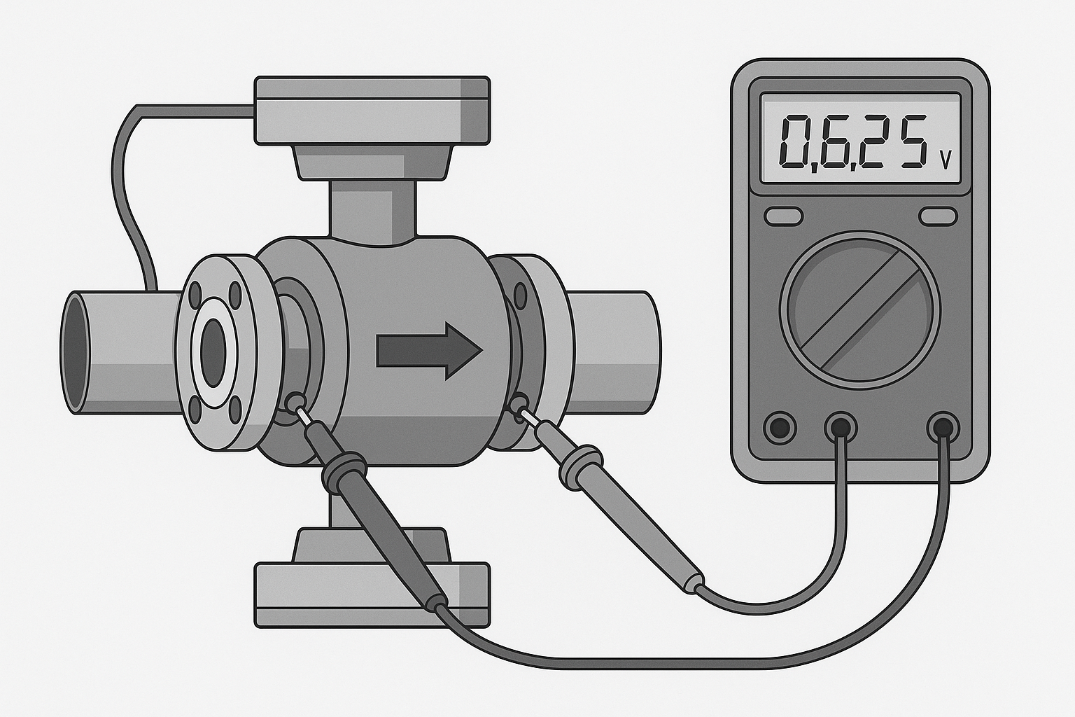
Check ball valve jumper continuity with a multimeter (contact resistance ≤ 0.1 Ω).
Calibration and Testing:
Temporarily rotate the probe 90° for zero-point calibration.
After repositioning, compare flow display with actual operating flow. If deviation > ±1%, use an ultrasonic flow meter for verification and adjust converter parameters accordingly.
3. Post-Maintenance and Acceptance
3.1 Site Restoration
Replace and seal the manhole cover.
Remove tools, debris, and barricades from the area.
Inspect the structural integrity of the access cover to ensure no safety hazards remain.
3.2 Operational Validation
Reopen the valve and restore flow.
Observe meter readings for abnormal noise, leakage, or vibration.
Record commissioning data and archive a formal maintenance report.
4. Typical Troubleshooting Cases
Case 1: Gradual Drop to Zero Flow Reading
Issue:
At a diesel engine facility using brine solution, the flow reading decreased gradually to zero after two months of inactivity.
Diagnosis:
Measured very low electrode resistance. Upon disassembly, yellow rust (iron oxide deposits) was found on the insulation liner.
Solution:
Cleaned deposits using approved cleaning methods. Flow returned to normal after reassembly.
Summary:
Conductive deposits shorted the electrodes. This fault developed gradually, so regular inspection is advised.
Case 2: No Display on the Meter
Issue:
Flow meter suddenly stopped displaying any values.
Diagnosis:
Power was normal. No current signal detected at the transmitter. Using a simulation signal (YR-100) revealed no response from the converter—fault traced to a failed converter.
Solution:
Sent the converter for factory repair due to lack of spares.
Summary:
When displays fail, first confirm power and check for disconnections or internal component failures.
Case 3: Display Shows Maximum Value and Alarm
Issue:
AXFA14 meter displayed full-scale flow with process alarm warnings and signal errors.
Diagnosis:
Detected disconnected ground wire after inspecting cable connections.
Solution:
Reconnected ground; fault cleared, and meter returned to normal.
Summary:
Grounding faults are common triggers for signal alarms. Always verify grounding continuity.
Case 4: New Meter Shows Over-Reading (~40% High)
Issue:
Newly installed split-type meter displayed ~40% higher than actual flow.
Diagnosis:
Converter and sensor were mismatched during installation.
Solution:
Matched correct converter and issue resolved.
Summary:
Ensure sensor and converter serial numbers match. Factory calibration is only valid when paired correctly.
Case 5: Severe Display Fluctuation
Issue:
Flow readings fluctuated by up to 50% of full scale.
Diagnosis:
All components seemed correct, but commissioning water was deionized.
Solution:
Replaced test fluid with tap water. Flow readings stabilized.
Summary:
Medium conductivity must meet meter design specs. Deionized water may cause instability.