Pressure transmitters are widely used in process industries to convert pressure signals of gases or liquids into standardized electronic signals (typically 4–20 mA DC). These signals are then transmitted to secondary instruments such as indicators, recorders, controllers, or DCS systems for process monitoring and control.
This guide summarizes practical maintenance insights, common troubleshooting procedures, and step-by-step repair methods for pressure transmitters.
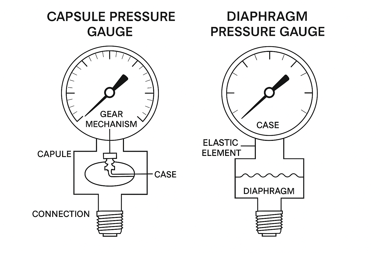
2. Working Principle and Classification
General Pressure Transmitters: Range 0.001 MPa – 20 MPa
Differential Pressure Transmitters: Range 0 – 1.5 kPa
Vacuum Transmitters: Below atmospheric pressure
Principle: The measured medium applies pressure to the high- and low-pressure chambers. The differential force displaces a diaphragm, which changes the capacitance between the sensing electrodes. This capacitance change is converted into an electrical signal proportional to the pressure, and then amplified into a 4–20 mA DC output.
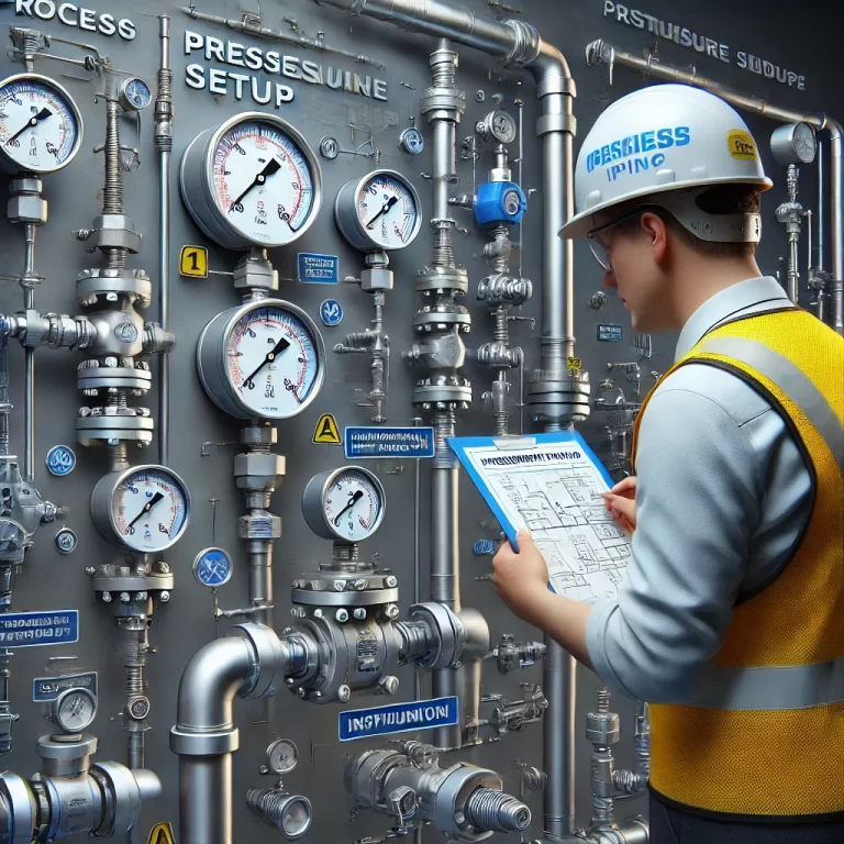
3. Routine Maintenance
3.1 Inspection Rounds
Verify if the local indicator or control room reading is within normal range.
Check for abnormal fluctuations.
Inspect for leaks, corrosion, dust accumulation, or loose fittings.
3.2 Periodic Checks
Perform zero checks using the three-valve or five-valve manifold.
Conduct venting, draining, and flushing of impulse lines.
Extend inspection intervals if no abnormalities are observed.
3.3 Major Overhaul
Prepare spare parts, replacement transmitters, and test equipment.
Clean impulse lines, drain condensate, and prevent freezing damage.
Calibrate transmitters after repair and document results.
4. Common Faults and Troubleshooting
4.1 Output Too High
Check measurement range and impulse line blockages.
Inspect for leaks, deposits, or incorrect valve positions.
Verify sensor grounding and circuit board functionality.
4.2 Output Too Low or No Output
Confirm supply voltage and loop resistance.
Check polarity and short circuits.
Inspect diaphragm, impulse line condition, and sensor continuity.
4.3 Unstable Output
Eliminate intermittent short circuits or grounding faults.
Adjust damping settings.
Remove trapped gas or liquid from impulse lines.
4.4 Valve Manifold Leakage
Replace sealing gaskets or O-rings.
Tighten nuts in a diagonal sequence with proper torque.
5. Maintenance and Repair Procedures
5.1 Disassembly
Remove the transmitter from process piping.
Carefully disassemble sensor module and clean diaphragm with neutral detergent (avoid chloride/acid solutions).
Detach electronic boards for inspection or replacement.
5.2 Reassembly
Check all O-rings and threads for integrity.
Apply sealing compound on threaded joints.
Tighten bolts diagonally with specified torque (e.g., 39–47 N·m).
Ensure correct alignment of high- and low-pressure ports.
6. Replacement and Interchangeability
Sensor Modules: Non-repairable; replace as a unit if damaged.
Amplifier & Calibration Boards: Interchangeable but require recalibration after replacement.
Indicator Heads: Can be rotated or replaced independently.
7. Safety Considerations
Always isolate the transmitter from process pressure before disassembly.
Disconnect power supply before opening the electrical housing.
Wear protective gloves when handling hazardous or radioactive media.
Collect and dispose of drained fluids according to environmental and safety regulations.
8. Tools and Equipment
Standard pressure generator
Reference manometer
Multimeter
Screwdrivers, wrenches, test hoses, and fittings
Cleaning solvents and lint-free cloth
9. Conclusion
Proper maintenance significantly reduces transmitter failures and extends service life. A systematic inspection plan, accurate fault diagnosis, and adherence to safety protocols are essential for ensuring measurement reliability in industrial processes.