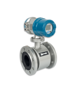
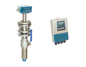
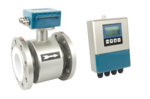
As with the usual meters, after the electromagnetic flowmeter is installed and wired, it should be checked whether the installation and wiring are correct and whether the meter can work normally.
It must be emphasized here that for some units lacking experience, the instrument installation and operation personnel should carefully read the relevant technical instructions in the relevant electromagnetic flowmeter installation and operation manual, and be good at analyzing and thinking about the problems encountered during the initial operation.
The whole set of electromagnetic flowmeters has been adjusted and calibrated on the flow calibration device of the manufacturer. As long as the matching number of the sensor and the converter and the meter coefficient is checked, it can be put into operation without any adjustment.
If a problem is found during the initial operation and needs to be adjusted on-site, do not operate blindly and mess up the entire set of instruments that have been adjusted.
Before the instrument is put into operation, the sensor must be filled with the actual measuring medium, and the zero point should be adjusted in a static state after power-on. After it is put into operation, it is necessary to stop the flow and check the zero point regularly according to the medium and use conditions. Especially for the non-clean medium that is easy to precipitate, easy to contaminate the electrode, and contains solids, check more in the early stage of operation to gain experience and determine the normal inspection cycle.
For qualified users, several basic parameters of the sensor should be measured and recorded before the instrument is put into operation:
- The insulation resistance of the electrode (when the sensor is empty, the insulation between the two resistances to the instrument case or the ground)
- Insulation resistance of the excitation coil (the insulation resistance of the excitation coil to the instrument case or ground)
- The cold resistance value of the excitation coil (that is, the copper resistance value of the enameled wire of the excitation coil)
- The contact resistance of the electrode, the sensor is filled with liquid, and the resistance between the electrode and the grounding terminal is measured. The contact resistance of the two electrodes should be roughly the same.
These data are very helpful for the analysis of the cause of the sensor failure after a period of operation.
For example, when the contact resistance of the two electrodes changes, it indicates that the electrodes are likely to be contaminated; the contact resistance increases and the contaminants may be insulating deposits; the contact resistance decreases, and the contaminants may be conductive deposits.
The contact resistance of the two electrodes is asymmetrical, indicating that the two electrodes are contaminated to different degrees: the decrease in the insulation resistance of the electrodes and the excitation coil indicates the degree of dampness of the sensor; when the insulation resistance drops to a certain level, it will affect the normal operation of the meter.
The cold resistance value of the excitation coil is a parameter to ensure the normality of the excitation coil.


