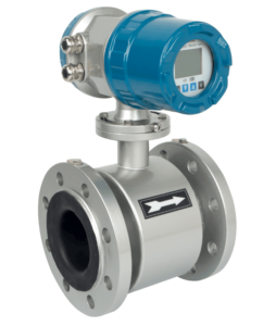
An electromagnetic flowmeter is formed by the combination of a transmitter and a flow sensor. The work of the flow sensor is to simply convert the volume flow of the conductive liquid that flows in the pipeline, and into the linear electrical signal.
The principle used for conversion is derived from Faraday’s Law of electromagnetic induction. Therefore, the electromagnetic wire is cut off through the magnetic field to help in the generation of electromotive force. The flow sensor’s magnetic field is derived by excitation, which is then divided into DC excitation and AC excitation, as well as low-frequency square wave excitation.
A lot of flow sensors nowadays use low-frequency square wave excitation. The transmitter mainly includes an excitation circuit, amplifying circuit, a microprocessor circuit, signal filtering, a D/A circuit, a transmission circuit, and an A/D sampling circuit, among others.
Applied Principle
The electromagnetic flowmeter, also known as EMF, is a 20th-century device. Approximately 50-60 years old, developed with electronic technology together with the rapid development of new flow instruments used for measurements. The electromagnetic flowmeter excitation is designed according to the law of Faraday regarding electromagnetic induction.
On the other hand, an electromagnetic flowmeter is used in measuring the volume flow of conductive liquid, and due to the unique benefits that it has, it has been used by most people in the measurement of flow in various conductive liquids in the industrial process.
Some examples include alkalis, acids, and corrosive media. Therefore, electromagnetic flowmeters come in handy when measuring several slurry flow rates, which is an application area that is essentially unique.
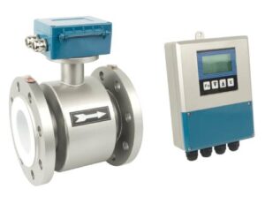
When it comes to structuring, an electromagnetic flowmeter features two parts which include the flow sensor and converter. Installation of the sensor happens on the industrial process pipeline, and its main objective is transforming the volumetric flow value of the flowing liquid in a linear manner, right into the pipeline, and into a potential signal-induced. This thereby sends the signal to the converter through the line of transmission.
Installation of the converter happens close to the sensor, and this helps to amplify the signal’s flow that is sent by the sensor, which then converts into just a simple electrical signal output that is standard and proportional to the signal’s flow for accumulation, adjustment, and display control.
Electromagnetic Flow Meter Basic Principle
Here are some of the basic principles of an electromagnetic flowmeter.
Measuring Principle
The Law of Faraday regarding electromagnetic induction states that when the lines of magnetic forces are cut by a conductor in a magnetic field, an induced electric potential is generated on either side of a conductor.
The right-hand rule is usually the one that determines the direction. When it comes to the magnitude, it is usually equal to the intensity of induction of B in the magnetic field. You should note that the conductor is the magnetic field, and the length L of the stipulated conductor is usually proportional to the speed U of your conductor.
Therefore, if B, L, and U are perpendicular to each other, then below is the equation:
E=BLU (3-35)
In the same magnetic field with a magnetic induction intensity of B, a non-magnetic pipe that has an inner diameter of D is perpendicularly placed in the magnetic field’s direction. When a flow of the conductive liquid takes place in the pipe at the flow rate of U, it cuts the force of the magnetic lines.
If there is an installation of a pair of electrodes on both ends of the pipe section perpendicular to the magnetic field’s diameter, it can be proved provided the velocity distribution flow in the pipe is in axisymmetric distribution. There is also the generation of an induced electromotive force between the 2 electrodes.
Below is the equation:
E=BD (3-36)
You can get the volume flow rate of the pipeline through the following equation:
QV= πDU=(3-37)
Looking at the formula above, you can clearly see that the volume flow QV comes with a linear relationship with the electromotive force e induced, and the inner diameter of the measuring tube D, which is inversely proportional to the magnetic field’s magnetic induction B, doesn’t have anything to do with all the other physical parameters. Therefore, that is the measuring principle used by electromagnetic flowmeter excitation.
Note that making the formula (3-37) to become relevant, the conditions for measurements are supposed to meet the assumptions below:
- The magnetic field is distributed uniformly and constantly
- Asymmetric distribution of the velocity flow of the fluid measured
- Test the non-magnetic fluid
- The tested liquid’s conductivity is isotropic and uniform
The Sketch of the Electromagnetic Flow Meter Principle
Requirements:
- Electrodes
- Magnetic pole
- Pipe
Excitation Method
This method generates the magnetic field. There are three excitation methods that you should know. They include:
DC Excitation
It is known as the Direct Current excitation method and it generates a permanent magnetic field, which helps to develop a uniform magnetic field constantly. The benefit of this method is that its transmitter is not affected as much by the interference of the AC electromagnetic field. Therefore, you can ignore the self-inductance influence in the liquid.
But, you can easily prioritize the use of a Direct Current magnetic field to generate both positive and negative ions. Ironically, the negative ions tend to run the positive pole, while the positive ions run the negative pole.

AC Excitation
This method is normally generated through sinusoidal alternating current. That means the magnetic field generated is alternating. Its benefit is that it alleviates polarization disturbance on the surface of the electrode.
The equation:
B=Bm SiN T ( .338 is)
Measured volume flow includes:
D=QV ( .340)
The angular frequency of the excitation current = 2F; t-time; f-power frequency
Low-Frequency Square Wave Excitation
People began using low-frequency square wave excitation to avoid the benefits and drawdowns of AC and DC excitation modes. Its frequency is 1/4 I/10 of the power.

Square wave’s excitation current waveform method
In just half the period, the magnetic field is stable and constant on the DC magnetic field. This has the characteristics of DC excitation, and luckily electromagnetic interference doesn’t affect it. Therefore, the square wave signal is one that is alternating to help overcome the polarization effect normally gotten from DC excitation.
Therefore, we would conclude that square wave excitation is an efficient method, and it’s been used widely in electromagnetic flowmeters.
Advantages of Electromagnetic Flow Meters
- Avoids orthogonal electromagnetic interference of the AC magnetic field
- Alleviates power frequency interference resulting from capacitance distribution
- It surpasses the eddy current gotten from the AC magnetic field in the fluid and pipe wall
- It gets rid of the DC excitation polarization