Overview
Indicator lights are essential components in electronic and electrical equipment, serving as intuitive visual interfaces that convey the operational status of systems through color changes, blinking, or specific display patterns. Typically utilizing LEDs or traditional incandescent bulbs as light sources, indicator lights work in conjunction with control buttons to visualize signals effectively. They play a vital role in user interfaces, providing clear feedback for power status, fault alarms, or operational commands.
1. Core Factors in Indicator Light Selection
Color Codes and Functional Mapping
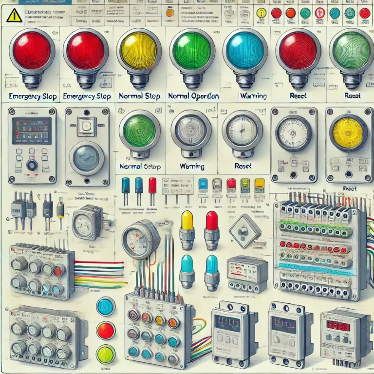
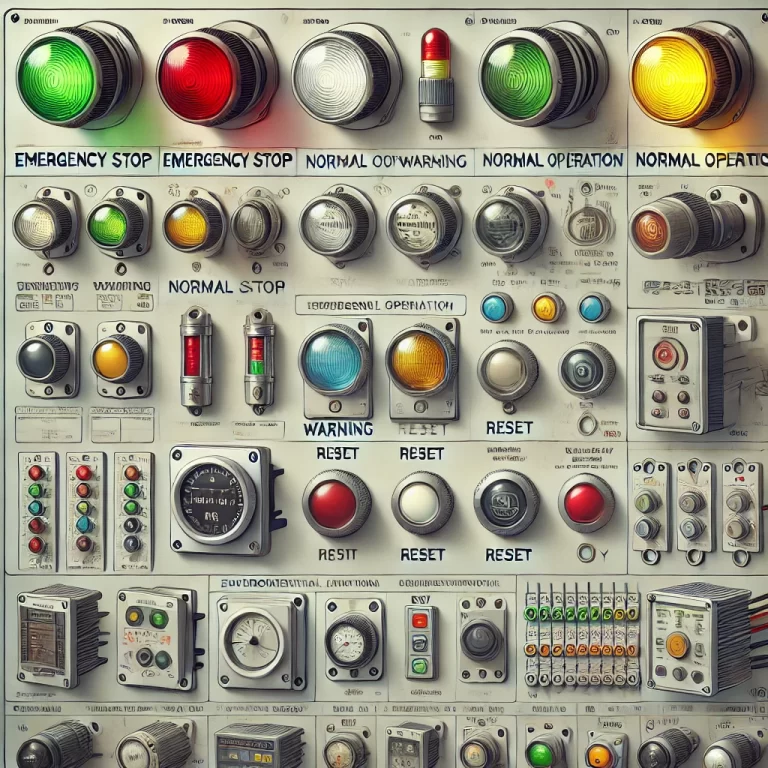
Red: Emergency stop, fault alarms (e.g., thermal relay activation), or power-off indication.
Green: Normal operation, successful start-up (e.g., contactor engaged); primarily used to indicate running status.
Yellow: Warning or transitional states (e.g., temperature anomalies, load fluctuations); often combined with buzzers for audiovisual alerts.
Blue: Specific operations (e.g., reset, parameter setting); should not be used for main circuit status.
White: General-purpose signal or neutral status (e.g., standby circuit energized).
Electrical Parameter Matching
Voltage Level: Must match the secondary circuit voltage; typically 220V AC for AC systems and 24V or 12V DC for DC systems.
Current Handling: LED indicators generally consume ≤1W; incandescent bulbs require attention to inrush current (e.g., 12V/0.5A).
Ingress Protection (IP) Rating: IP65 recommended for industrial environments (dust- and water-resistant); IP20 acceptable inside control cabinets; stainless steel housings needed for corrosive environments.
2. Key Performance Indicators
Environmental Adaptability Requirements
| Parameter | Industrial Grade | Consumer Grade |
|---|---|---|
| Operating Temperature | -25℃ to +70℃ | 0℃ to +50℃ |
| Humidity Resistance | 95% RH (non-condensing) | 85% RH |
| Mechanical Shock Resistance | 30G/11ms | 10G/6ms |
Optical Performance Optimization
Optical parameters are crucial for effective visual signaling:
Brightness (Luminous Flux, lm): Determines visibility under various ambient lighting conditions.
Viewing Angle (°): Wider angles allow better visibility from different perspectives.
Color and Purity: Accurate, vivid colors help users quickly distinguish different states. High color fidelity is critical in specialized fields like medical devices and aerospace.
Design Tip: For dim environments or long-distance observation, choose high-brightness, wide-angle indicators. For color-critical applications (e.g., control panels in aviation), prioritize models with precise and consistent color reproduction.
3. Selection Process and Implementation Steps
Four-Step Selection Method
Step 1: Environment Assessment
Record ambient temperature fluctuations, dust levels, and chemical exposure.
Determine appropriate IP rating and material type.
Step 2: Electrical Parameter Validation
Measure control circuit voltage fluctuation (±10%).
Choose wide-voltage range LED indicators (e.g., DC 9-36V models).
Step 3: Functional Requirements Confirmation
For interlocking operations, select self-locking type illuminated pushbuttons (e.g., LA38-11D series).
Step 4: Certification Verification
Check for mandatory certifications: CCC (China), UL (North America), CE (Europe).
Explosion-proof environments require ATEX certification.
Installation Guidelines
Spacing Standard: Horizontal spacing ≥50mm, vertical height difference ≤10mm (ergonomic compliance).
Wiring Requirements: Use crimped OT terminals for stranded wires; ground wires must be yellow-green and ≥2.5mm² cross-section.
4. Typical Application Scenario
4.1 Case Study: Automated Production Line
Conditions:
Environment: −20℃ to +50℃, high humidity, mild corrosive gases.
Electrical: 24V DC system, maximum load 0.5A.
Appearance: Compact size; red, green, and yellow colors required.
Functional: High brightness; durable performance for at least three years in harsh conditions.
Selection Recommendation:
Choose tri-color LED indicator lights with IP67 protection.
Use materials resistant to corrosion, such as stainless steel housing or PC/PA plastics.
4.2 Tailored Selection Advice
Environmental Adaptability: Prioritize materials resistant to temperature extremes, humidity, and corrosive gases.
Product Series: For aesthetic requirements, consider LED backlit models or illuminated pushbuttons.
Technical Specification Comparison: Opt for high-efficiency, low-power consumption models to reduce long-term costs.
5. Maintenance and Troubleshooting Guide
Routine Maintenance
Cleaning Cycle: In dusty environments, clean the lamp cover monthly using isopropyl alcohol.
Lifetime Management: LED indicators typically last 50,000 hours; inspect for brightness decay (>30% drop) every three years and replace if necessary.
Common Fault Solutions
| Fault Symptom | Possible Cause | Solution |
| Indicator glows dimly | Excessive leakage current (>0.5mA) | Check insulation resistance (≥10MΩ) |
| Color distortion | LED chip aging | Replace with modules from the same batch |
| Button stuck | Dust ingress into mechanical parts | Dismantle, clean, and apply silicone grease |
6. Conclusion and Future Outlook
Modern low-voltage assemblies are moving toward smart and integrated indicator solutions. Notable trends include:
IoT Integration: Indicator lights supporting MODBUS protocol, enabling remote control and mode adjustments via PLC systems.
Self-Diagnostic Functions: Built-in temperature sensors that automatically dim the light and trigger alarms in case of overheating.
Practical Application Examples:
Smart Factories: Indicator lights networked with MES (Manufacturing Execution Systems) for real-time production status visualization.
Power Grids: Intelligent indicators in substations for remote fault monitoring.
Building Automation: Integration with BMS (Building Management Systems) for environmental monitoring and safety alarms.
Selection Advice: Always anticipate future system upgrades. Choose modular designs (e.g., Weidmüller SCM series) that offer expansion interfaces for future digital transformations.