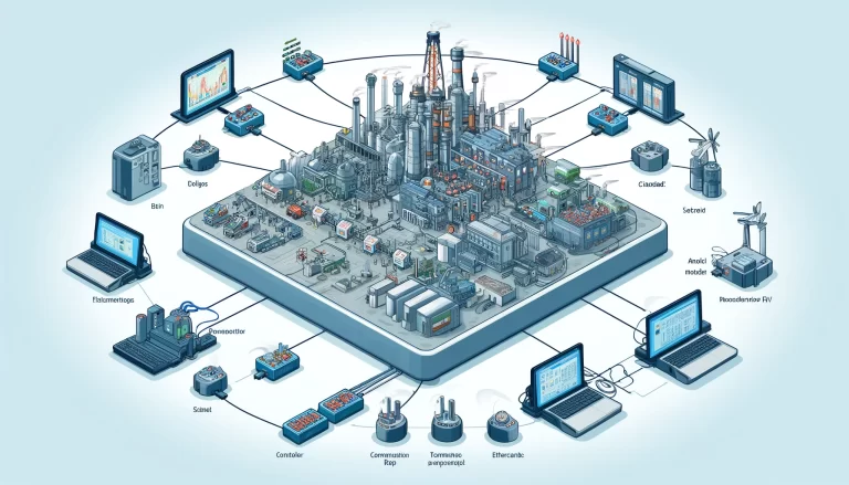
PLC (Programmable Logic Controller) installation and wiring are critical processes in ensuring the reliable operation of an automated control system. Improper installation or wiring can lead to malfunction, system failure, or even safety risks. This article provides a detailed guide on the essential considerations when installing and wiring a PLC system.
1. Choosing the Right Installation Location
Environmental Conditions:
The PLC should be installed in a clean, dry, and well-ventilated area. This is to prevent exposure to dust, moisture, or corrosive substances, which could damage the system. Additionally, the installation site should not be directly exposed to sunlight or extreme temperatures. The recommended ambient temperature for PLCs typically ranges from 0°C to 55°C, and the humidity should not exceed 85%. For installations in particularly harsh environments, it may be necessary to place the PLC in a sealed, air-conditioned cabinet.
Vibration Control:
PLCs are sensitive to vibration, which can cause connections to loosen or the device to malfunction over time. It is important to avoid installing the system in areas with significant mechanical vibration. If vibration cannot be avoided, installing shock absorbers or vibration-dampening materials on the PLC’s mounting surface is advisable.
Dust and Water Protection:
PLC systems are typically housed in control cabinets, and it’s crucial to ensure that these cabinets meet appropriate ingress protection (IP) ratings. The IP rating should match the environmental demands, with higher ratings like IP65 or IP66 providing better protection against dust and water ingress.
2. Power Supply Wiring
Dedicated Power Supply:
For reliable operation, the PLC should have its own dedicated power supply. Sharing the power source with high-power devices such as motors or industrial equipment can introduce electrical noise or cause voltage fluctuations, which can interfere with the PLC’s operation. It is also recommended to use a stable, regulated power supply for the PLC to avoid damage from power surges or sags.
Grounding:
Proper grounding of the PLC system is essential for reducing electrical noise and preventing damage from power surges. The PLC’s ground terminal should be connected to a stable earth ground, and the ground resistance should generally be less than 10 ohms. Use a short, thick ground wire to minimize resistance. Additionally, it’s important that all grounding is done at a single point to prevent ground loops, which could introduce noise or lead to malfunction.
Separation of Power and Signal Lines:
To minimize electromagnetic interference (EMI), the power lines (especially AC power lines) should be routed separately from signal or communication lines. A general rule is to maintain a separation distance of at least 10-15 cm between power and signal cables. In the case of high-voltage power cables, this distance may need to be increased further, and shielded cables should be used for the signal lines to ensure proper noise isolation.
3. Signal Wiring
Using Shielded Cables:
All input and output signal cables should be shielded to protect against electromagnetic interference (EMI), which can cause erratic behavior in the PLC. The shielding should be grounded at one end, typically near the PLC to ensure effective noise reduction. It is important that the shield is not grounded at both ends to prevent the creation of a ground loop, which can cause interference.
Neat and Organized Wiring:
Signal wires should be neatly organized to prevent tangling, short circuits, or accidental disconnection. Avoid running signal wires alongside power cables to minimize potential interference. Routing signal lines through separate conduits or cable trays from power lines is a good practice. Additionally, ensure that analog signal cables (e.g., 4-20 mA or 0-10 V signals) are kept separate from digital signal cables to prevent cross-talk.
Protecting Analog Signal Lines:
Analog signals are particularly sensitive to noise, so it is advisable to use twisted-pair shielded cables to further protect them from interference. Additionally, placing the analog lines in grounded metal conduits may be necessary in environments with significant electrical noise or proximity to high-power machinery.
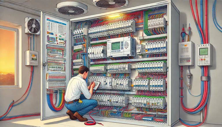
4. Input/Output Terminal Wiring
Correct Wiring Sequence:
The input/output (I/O) terminal wiring should strictly follow the wiring diagram provided by the system design. This ensures that inputs (e.g., sensors, switches) and outputs (e.g., actuators, relays) are correctly connected to the PLC. It is also important to verify that the type of input (AC/DC) matches the specifications of the PLC’s input modules. Incorrect wiring can result in short circuits, overvoltage, or failure of the I/O modules.
Short Circuit Prevention:
To avoid short circuits, it’s essential to keep input and output terminals properly isolated. Use terminal blocks or labeled connectors for easy identification and separation of wires. Additionally, using terminal covers or separators can help prevent accidental contact or short circuits between terminals.
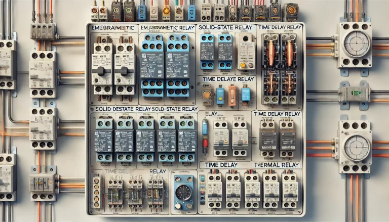
I/O Protection:
Installing protection devices like diodes, varistors, or fuses on I/O terminals is essential to protect the PLC from potential overloads or voltage spikes. This is particularly important when controlling inductive loads such as solenoids, motors, or relays. For higher voltage or current signals, using opto-isolators or relays can provide additional isolation and prevent damage to the PLC’s internal circuits.

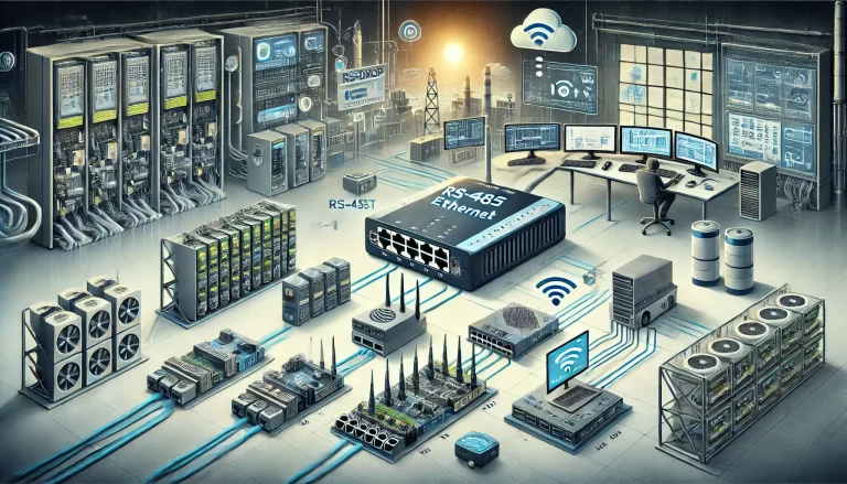
5. Communication Line Wiring
Specialized Communication Cables:
For PLCs that need to communicate with other devices or systems, using the correct communication cables is essential. For example, RS232, RS485, or Ethernet cables should be selected according to the communication protocol being used. Using the manufacturer’s recommended cables ensures the best performance and reliability.
Signal Amplification for Long-Distance Communication:
For communication over long distances, signal degradation or attenuation can occur. In such cases, consider using signal amplifiers or repeaters to maintain signal integrity. For Ethernet-based communication, the recommended maximum distance for a single segment is 100 meters; beyond this, switches or repeaters should be used.
Communication Line Interference Mitigation:
As with signal lines, communication lines should be kept separate from high-power cables to prevent EMI. Where possible, use shielded twisted-pair cables or fiber optic cables for long-distance communication to further reduce susceptibility to interference.

6. Ventilation and Heat Dissipation
Adequate Ventilation:
PLC control panels and cabinets should have adequate ventilation to prevent the system from overheating. Many PLC modules generate heat during operation, and excessive heat can reduce their lifespan or cause malfunctions. Installing ventilation fans or air-conditioning systems in the control cabinets may be necessary, especially in hot environments or when the system is installed in an enclosed space.
Monitoring Temperature:
If the PLC operates in a high-temperature environment, consider installing temperature sensors or monitoring devices within the cabinet to ensure the internal temperature remains within the PLC’s operating range. Proper heat dissipation mechanisms, such as heat sinks or fans, should be employed for high-power modules.
7. Labeling and Identification
Clear Labeling:
All wires, terminals, and components should be clearly labeled. Using standardized labels ensures that each wire and connection point can be easily identified, which is especially useful during maintenance, troubleshooting, or future system upgrades. Labeling also reduces the likelihood of miswiring or incorrect reconnections during repairs.
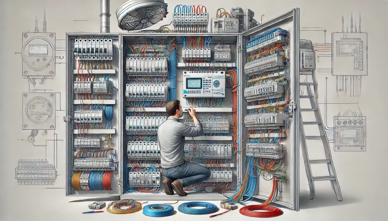
Maintaining Wiring Diagrams:
A complete and accurate wiring diagram should be maintained and stored in a convenient location, such as inside the control cabinet door. This helps technicians quickly understand the system’s wiring layout and make modifications or repairs as needed.
8. Testing and Commissioning
Wiring Verification:
After wiring is complete, it is essential to test the continuity and insulation of all cables to ensure that there are no short circuits, loose connections, or open circuits. Tools like multimeters, signal generators, or insulation testers can be used for this purpose.
System Debugging:
Before powering up the system, conduct a dry run to verify that the PLC logic and control program are functioning correctly. During this phase, all inputs and outputs should be tested, and any discrepancies should be corrected. After testing, the system can be powered on in stages, with real-world inputs and outputs gradually introduced to ensure smooth operation.
Conclusion
Proper installation and wiring of a PLC system are critical to ensuring reliable and safe operation. By following best practices in power supply design, grounding, signal separation, and protection, as well as ensuring proper labeling and testing, you can minimize the risk of system failure and maximize the longevity and efficiency of the system. These guidelines help ensure that the PLC performs its intended functions while reducing downtime and maintenance costs.