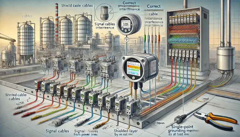
Integrated temperature and pressure gauges—also known as dual-function indicators—are widely used in chemical, pharmaceutical, and energy sectors for real-time monitoring of both temperature and pressure in a single instrument. Prices vary significantly depending on specifications, structure, and application environments, ranging from budget-friendly mechanical models to high-end versions with electronic outputs and rugged construction.
This article explores the main factors that affect pricing and performance, common failure modes, and best practices in installation and maintenance.

1. Price Segmentation and Value Drivers
The market for integrated temperature-pressure gauges can generally be segmented into the following tiers:
| Tier | Price Range | Typical Features |
|---|---|---|
| Entry-Level | $15–50 | Mechanical pointer type, low accuracy, no output |
| Mid-Range | $50–200 | Stainless steel housing, basic 4–20mA or Modbus signal |
| High-End | $200–1000+ | Explosion-proof, digital display, remote transmission |
Key factors driving price differences include:
Sensor Type and Accuracy: Bimetallic temperature elements are cheaper but less accurate than RTD or thermocouple types. Pressure measurement may be mechanical or piezoresistive.
Housing and Wetted Materials: Instruments made from stainless steel 316 or with PTFE linings for corrosive media cost significantly more.
Signal Output: Analog (4–20mA), Modbus RTU, or HART communication adds both functionality and cost.
Explosion-Proof Design: Essential for use in flammable environments, but greatly increases cost due to stringent testing and certification.

2. Common Installation Issues That Affect Performance
2.1 Insufficient Insertion Depth
If the sensing element (e.g., bimetallic strip) is not fully immersed in the medium, the reading will reflect only the surface or partial temperature, especially in pipelines. As a rule of thumb, the probe should be inserted at least 1/3 to 1/2 of the pipe diameter, or as per manufacturer guidelines.
2.2 Improper Mounting Position
Avoid mounting the gauge near valves, elbows, or turbulent flow zones where temperature and pressure fields may fluctuate, leading to unstable readings. Exposure to vibration can also cause mechanical displacement, leading to inaccurate readings or pointer jamming.
2.3 Ambient Temperature Effects
Prolonged exposure to extreme external temperatures (e.g., direct sunlight, freezing weather) can cause heat conduction through the casing, disrupting the internal mechanics—particularly in non-hermetically sealed instruments.
3. Media Characteristics and Measurement Challenges
3.1 Corrosive or Abrasive Fluids
Such media can degrade sensing elements, changing elasticity and thickness of bimetallic strips, increasing long-term error. Use protective sheaths like 316L stainless steel or ceramic coatings for corrosive conditions.
3.2 Fluid State Anomalies
Gas bubbles or stratification in liquids can produce inconsistent readings. In highly viscous or solidifying media, the sensor may be insulated, slowing heat transfer and response time.
3.3 Operating Beyond Rated Range
Extended exposure to temperatures or pressures near or beyond the gauge’s limit can permanently deform components, leading to drift or failure.

4. Maintenance and Usage-Related Errors
4.1 Lack of Calibration
Mechanical gauges experience fatigue and wear over time. Annual calibration is recommended to maintain accuracy.
4.2 Mechanical Failures
Pointer misalignment, gear damage, or poor lubrication may prevent proper operation. Intrusion of dust or moisture can also corrode parts and jam the mechanism.
4.3 Signal Transmission Issues
For models with signal output (4–20mA, Modbus), loose wiring or module faults can distort the transmitted data, resulting in mismatch with actual readings.
5. Environmental and Electromagnetic Interference
5.1 Heat Radiation or Solar Gain
Installing the gauge near heat sources or in direct sunlight can skew internal readings due to heat transfer through the casing.
5.2 Vibration and EMI
Strong vibrations may shake internal mechanisms or loosen the pointer. While mechanical types are immune to EMI, versions with signal transmitters can be affected by nearby motors or inverters.
6. Design and Selection Mistakes
6.1 Improper Range and Resolution
Selecting a range too wide (e.g., measuring 60°C using a 0–300°C gauge) can reduce resolution and amplify reading errors. Match range closely to expected process values.
6.2 Incompatible Mechanical Design
For example, selecting a radial instead of an axial mount, or choosing a fixed probe length that doesn’t suit your vessel, can hinder accurate sensing.

7. Recommendations for Reliable Performance
| Area | Recommendation |
|---|---|
| Installation | Ensure correct insertion depth and stable mounting. Avoid turbulence and high-vibration zones. |
| Selection | Choose materials and output functions based on media type, accuracy needs, and environment. |
| Maintenance | Schedule annual calibration, inspect for corrosion or misalignment, and clean the instrument regularly. |
| Protection | Use sunshades, anti-vibration mounts, or protective sheaths in harsh environments. Avoid exceeding rated range. |

Conclusion
The performance and lifespan of integrated temperature and pressure gauges are highly dependent on correct selection, installation, and maintenance practices. While budget models may suffice for general-purpose applications, critical industrial processes demand high-precision, corrosion-resistant, and communication-enabled versions. Understanding these influencing factors is essential for making informed procurement decisions.
