1. Introduction
In the fields of industrial automation and fluid control, process connections are critical for ensuring secure installation, excellent sealing performance, and safe operation of equipment. The Japanese Industrial Standards (JIS) system provides a unique approach to flange connections, differing from ANSI and DIN standards commonly used internationally. JIS flanges are widely adopted in Japan and other parts of Asia for a variety of industrial systems.
2. Basic Concept of JIS Flange Process Connections
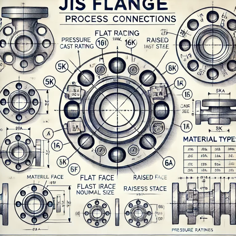
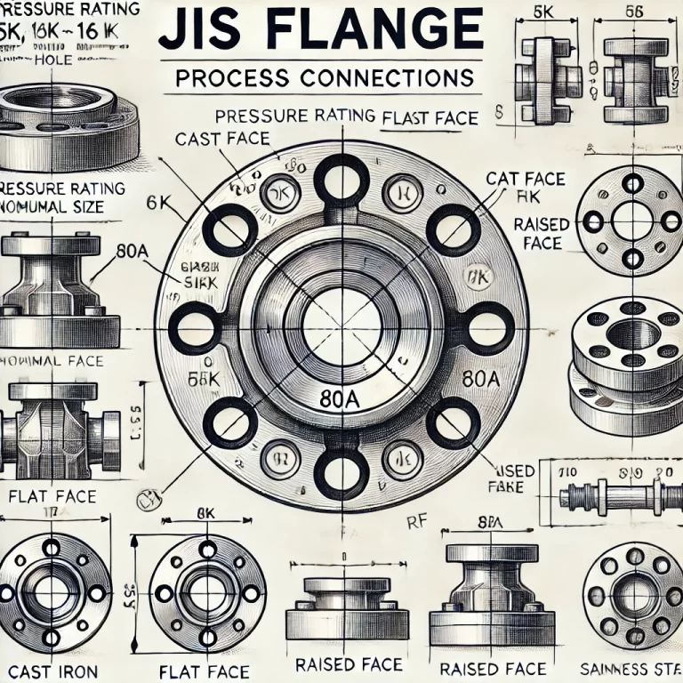
A JIS flange is typically specified by a combination of pressure rating, nominal pipe size, flange type, and material designation. The standard format is structured as follows:
Format: JIS XXK XXA
Where:
JIS: Indicates compliance with the Japanese Industrial Standards.
XXK: Represents the pressure rating (unit: kgf/cm²).
XX: Denotes the nominal pipe size (unit: mm).
A: Specifies the sealing face type, such as:
FF (Flat Face)
RF (Raised Face)
F/S: Indicates the flange material:
F for cast iron
S for stainless steel
Example: JIS 10K 80A FF
10K: Pressure rating of 10 kgf/cm² (~1.0 MPa)
80A: Nominal Diameter (DN80, approximately 3 inches)
FF: Flat Face sealing surface
Note: Surface finish requirements, especially for forged flanges, are controlled to ensure proper gasket sealing.

3. Technical Characteristics
3.1 Pressure Ratings
JIS flanges come in various pressure classes:
5K: ~0.5 MPa
10K: ~1.0 MPa
16K: ~1.6 MPa
20K: ~2.0 MPa
30K: ~3.0 MPa
40K: ~4.0 MPa
The “K” designation reflects pressure in kgf/cm². A higher K rating indicates a flange suitable for higher-pressure applications.
3.2 Nominal Size
DN80 (80A) corresponds to a nominal bore size of 80mm, commonly used in moderate flow applications such as cooling water systems or gas transportation pipelines.
3.3 Sealing Face Type
Flat Face (FF):
The flange face is smooth and flat.
Typically used with flat gaskets.
Suitable for low to medium pressure applications.
Advantages: Simple gasket seating, lower surface pressure requirements.
Disadvantages: Slightly lower sealing performance compared to RF.
Raised Face (RF):
A small raised area around the bore improves gasket compression.
Provides enhanced sealing under higher pressures.
3.4 Flange Material
JIS flange materials are classified based on application needs:
SUS304/SUS316: Stainless steel options for corrosion resistance.
FC200: Cast iron for general purposes.
SC450: Carbon steel for higher strength applications.
The “A” code in the example specifies a general material class, but detailed material confirmation is needed based on manufacturer datasheets.
4. Comparison with ANSI and DIN Flange Standards
| Aspect | JIS Flange | ANSI Flange (ASME B16.5) | DIN Flange (EN 1092-1) |
|---|---|---|---|
| Pressure Classes | 5K, 10K, 16K, 20K, 30K, 40K | 150LB (~1.0 MPa), 300LB, 600LB | PN10, PN16, PN25, PN40 |
| Sealing Face Types | FF, RF | RF, RTJ | FF, RF |
| Bolt Hole Arrangement | Different from ANSI/DIN | Standardized | Standardized |
Important Notes:
Bolt Pattern Differences: JIS bolt hole layouts do not align perfectly with ANSI or DIN flanges.
Interchangeability: Direct replacement between standards is not recommended without flange adapters or custom-designed flanges.
Example:
A JIS 10K flange bolt circle diameter (BCD) and hole size differ from an ANSI 150LB flange of the same nominal size.

5. Practical Considerations for Using JIS Flanges
When selecting a flange for international projects, confirm whether JIS standards are acceptable.
If integration with ANSI or DIN systems is required, plan for adapters or ensure precise machining.
Pay attention to gasket selection:
For FF flanges: full-face gaskets.
For RF flanges: ring gaskets.
Verify material compatibility based on process media (e.g., corrosive fluids may require SUS316L flanges).
6. Conclusion
The JIS flange system provides a practical and reliable solution for process connections across many industries, particularly in Asia. Compared to ANSI and DIN standards, JIS flanges offer different pressure classes, sealing methods, and dimensional characteristics. A clear understanding of these differences is crucial to avoid installation errors and ensure system integrity.
For industrial companies, mastering JIS flange specifications enhances equipment selection accuracy and prevents costly rework in multinational projects, ultimately improving system reliability and safety.
If you have any questions regarding process connections, flange selection, or instrumentation integration, feel free to contact our technical team for expert assistance.
