1) Concept & Scope
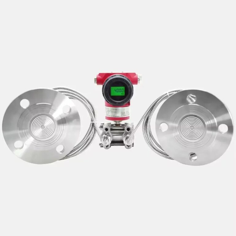
Interface level means the height of the boundary between two immiscible liquids of different densities (e.g., oil–water). A dual-flange remote-seal differential pressure transmitter infers the interface height from the pressure difference created by the two liquids across the measurement span. Typical uses: separators, coalescers, desalters, and oil–water interface tanks.
2) Media Requirements
Sufficient density contrast: Avoid pairs with very similar densities; measurement resolution and stability will suffer.
Stable densities: Large density drift with temperature/composition change degrades accuracy; consider temp compensation or narrower operating envelopes.

3) Installation Positioning
Liquid head above the upper flange: Keep the process liquid level always higher than the upper tapping to prevent level and interface moving together, which breaks the DP relationship. Do not allow a third phase (e.g., gas blanket or emulsion band) between the two flanges.
Transmitter elevation: Install the transmitter as close as practical to the tappings and preferably below the lower (high-pressure) flange for easier maintenance and reduced thermal effects on capillaries. Per SH/T 3104-2013 §8.4.8, when mounting above the lower tapping, verify by calculation that the capillary fill fluid will not vaporize.
Environment: Choose locations with minimal vibration, moderate temperature swing, and low corrosion risk—or add protective measures (coatings, enclosures).

4) Capillary & Remote Seal Handling
Length management: Excessive capillary length adds thermal-induced zero shifts. For long runs or difficult routing, consider an electronic remote interface level meter instead of very long capillaries.
Minimum bend radius: ≥ 50 mm. Follow mechanical protection and routing good practice. (GB 50093-2013 §6.1.12.)
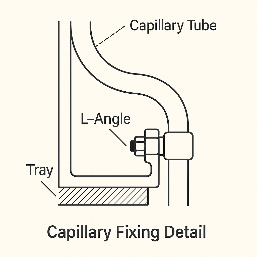
Rigid fixing: Support any free-span capillary on L-angle (e.g., 40/50) or tray to prevent wind-induced oscillation and stress on seals.
Thermal control: If local extremes approach the fill-fluid pour/boiling points or ambient varies rapidly, add insulation or heat tracing to keep fill-fluid single-phase and stable. SH/T 3104-2013 §8.4.6 also recommends fixing capillaries with angle steel and applying heat-trace/insulation where needed.

5) Mechanical & Protection Details
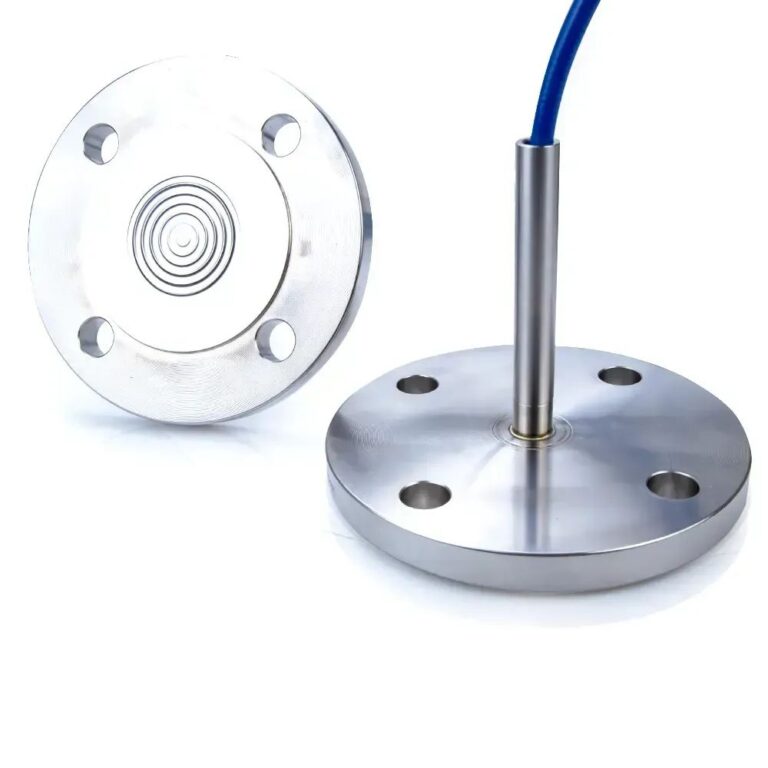
Gasketing: Select gasket type/size carefully; avoid any extrusion into the seal diaphragm area that can bias pressure transmission.
Bolting: Tighten in a cross pattern to ensure flatness and even gasket load; re-torque after thermal soak where applicable.
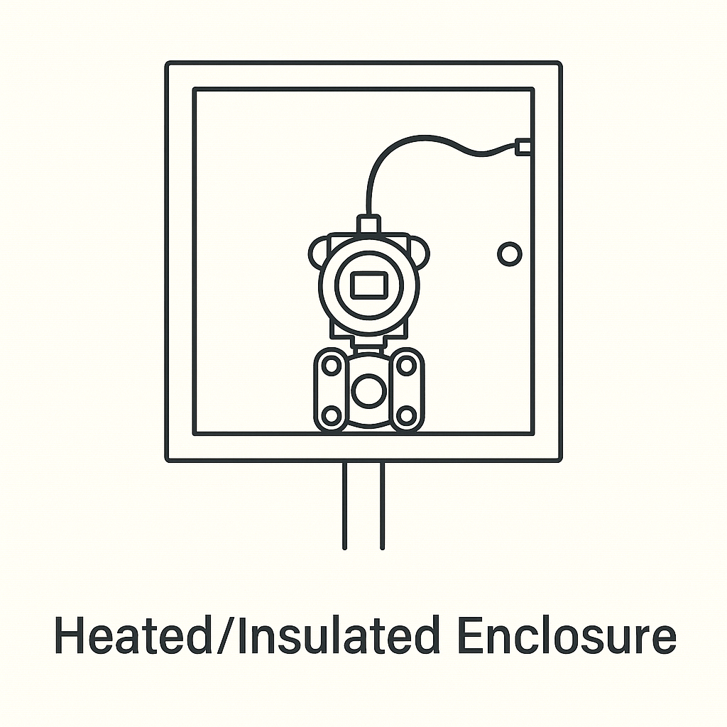
Weather protection: For outdoor installs, use a heated/insulated instrument enclosure so the electronics and LCD operate within rated temperature and ingress protection.
6) Configuration & Commissioning Checklist
Collect process data
ρ_heavy (e.g., water/brine), ρ_light (e.g., oil) at operating temperature(s)
Expected interface range and overall liquid head above upper flange
Range & LRV/URV
Calculate DP at 0% (all light) and 100% (all heavy) interface conditions including remote-seal head corrections and capillary orientation.
Compensations
Consider temperature effects on ρ and on capillary fill fluid; enable temp compensation if available.
Zero check
With stable fluid conditions, verify zero/span; note any offset from ambient gradients and adjust trim within limits.
Response & damping
Set damping to suppress slugs/emulsion waves without masking real movement.
Functional test
Simulate interface movement (controlled draining/filling or portable column) to confirm linearity and end-points.

7) Common Failure Modes & Fixes
Capillary thermal imbalance → drifting zero
Fix: Insulate/heat-trace both capillaries symmetrically; avoid routing one near hot equipment, the other in shade.
Third phase in the leg (gas pocket/emulsion)
Fix: Reposition tappings; ensure continuous liquid column; consider baffles or stilling wells.
Seal diaphragm distortion from gasket/bent bolts
Fix: Correct gasket selection and cross-torque; replace damaged seals.
Vibration-induced noise
Fix: Add supports; relocate transmitter; increase damping within response requirements.
8) Interface DP—Engineer’s Quick Reminder
For a vertical two-liquid column spanning the two flanges:
Let h = height of heavy phase in span; H = center-to-center distance between flanges.
DP ≈ g [ρ_heavy · h + ρ_light · (H − h)] + (remote-seal/capillary head corrections).
Solve for h across 0–H to map to 0–100%.
Always incorporate: transmitter elevation differences, seal fill fluid heads, and actual tap elevations per P&ID/GA.

9) When to Prefer Alternatives
Very small Δρ (near-miscible fluids), long/uneven capillaries, or extreme/rapid ambient swings → consider displacer with density compensation, guided-wave radar (GWR) for interfaces, or electronic remote DP solutions.
10) Data You Should Request/Record (Spec Template Snippet)
Service: tank ID, fluid pair, operating T/P ranges
ρ_light @ °C, ρ_heavy @ °C; expected emulsion thickness
Tap elevations (upper/lower), H distance, nozzle IDs
Seal type/size/materials; fill fluid type; capillary length & routing plan
Enclosure: IP/NEMA rating; heater/insulation plan; ambient design min/max
Damping & output (4–20 mA/HART/FF), hazardous area approvals

11) Field Notes — Do/Don’t Summary
Do
Keep upper tap submerged at all times
Fix capillaries on angle steel; bend radius ≥ 50 mm
Match thermal environments for both capillaries
Use cross-pattern bolting and correct gaskets
Provide weather/thermal protection for outdoor units
Don’tRoute one capillary across a hot pipe and the other in shade
Allow gas pockets or a third phase between taps
Overtighten bolts near seal diaphragms
Exceed capillary length without evaluating electronic alternatives
(All aligned with the cited installation norms and construction/QA guidance.)
