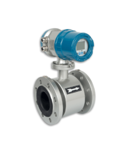
The electromagnetic flow sensor lining made of polytetrafluoroethylene (PTFE) pipe is generally not glued to the wall of the sensor measuring tube, so it is sensitive to vacuum negative pressure.
The vacuum in the pipeline will deflate the PTFE lining, making the lining arched in a wave-like shape—a typical negative pressure damage pattern. This destroys the seal of the electrode and the sensor cannot work.
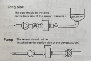
Therefore, PTFE-lined sensors cannot be used in negative pressure systems and should be installed in places where instant negative pressure may occur as much as possible.
For example, the sensor should not be installed on the suction side of the pump; the gate valve should be installed on the backside of the sensor, as shown in the figure, some PTTFE lined sensors can bear some negative pressure, but it is related to the temperature of the measured medium.
Therefore, the maximum value of temperature and vacuum that can withstand during operation should refer to the instructions of each manufacturer.
In addition, the PTFE flanging surface part should not be damaged or cut off, otherwise, the medium will flow into the back of the lining and damage the insulation. In order to protect the lining flanging, some manufacturers cover protective grounding rings on the flanges on both sides of the PTFE lining sensor to prevent accidental damage to the PTFE flanging, and should not be removed during installation. The material of the protective grounding ring can be selected according to the corrosion of the measured fluid.
It is well known that PTFE (cold state) deforms under pressure. During installation, flange bolts cannot be tightened arbitrarily without restriction. If the bolts are tightened too tightly, the PTFE creep will cause leakage at the flange connection, so the connecting bolts should be tightened with a torque plate, and the maximum tightening torque of the connecting bolts should be in accordance with the manufacturer’s instructions.
Maximum tightening torque of connecting bolt
| Diameter DN | Pressure/MPa | Bolt & quantity | Maximum torque | |
| N*m | kgf*m | |||
| 25 | 4 | 4*M12 | 22 | 2.2 |
| 50 | 4 | 4*M16 | 55 | 5.5 |
| 80 | 4 | 8*M16 | 47 | 4.7 |
| 100 | 1.6 | 8*M16 | 39 | 3.9 |
| 150 | 1.6 | 8*M20 | 68 | 6.8 |
| 200 | 1 | 8*M20 | 84 | 8.4 |
| 300 | 1 | 12*M20 | 88 | 8.8 |