Proper installation of measurement and pneumatic signal lines is essential for ensuring instrumentation accuracy, system safety, and long-term reliability. This document outlines key considerations and best practices during layout and installation.
1. Environmental and Routing Considerations
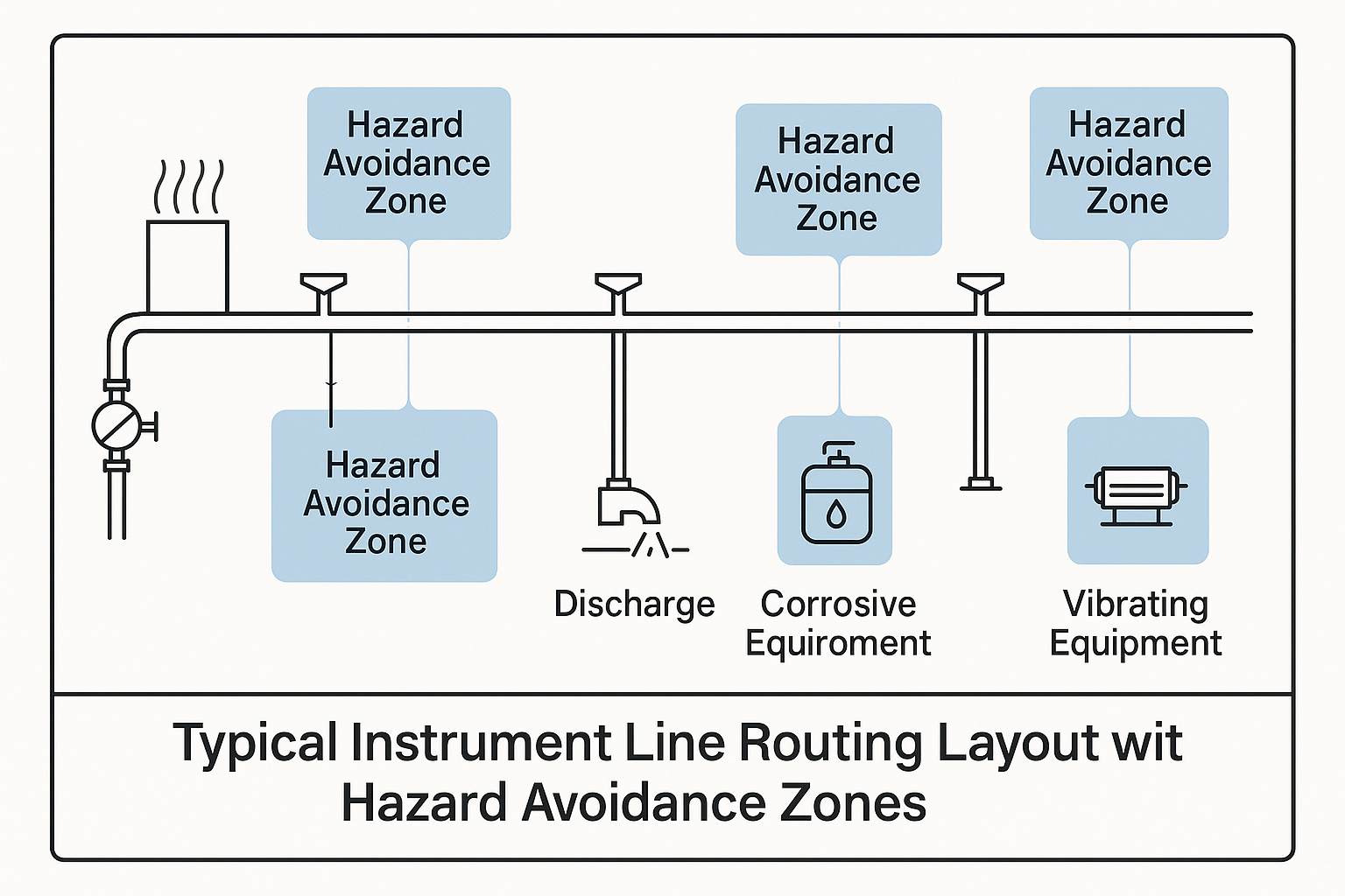
Avoidance of Hazards: Measurement and pneumatic signal lines should be routed away from high-temperature areas, corrosive environments, process venting points, mechanical vibration sources, and locations that obstruct maintenance activities.
Overhead Routing: Lines should be installed overhead whenever possible. Fixing should be secure and stable, minimizing unnecessary bends and crossovers.
Thermal Management: For media prone to freezing, condensing, solidifying, crystallizing, or vaporizing, apply heat tracing or thermal insulation to maintain line integrity.
🔧 Illustration 1: Typical Instrument Line Routing Layout with Hazard Avoidance Zones
2. Hydraulic and Pneumatic Performance Optimization
Static Head & Air Pockets: Layout should minimize additional static pressure heads, density variations, and trapped air or gas pockets within the measurement lines.
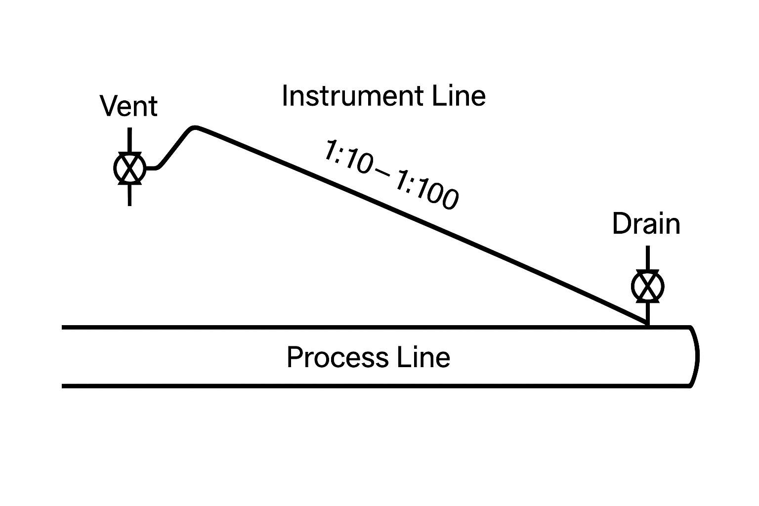
Slope Requirements: When installing horizontally, maintain a downward slope of 1:10 to 1:100 to facilitate fluid drainage or gas venting.
Drain/Vent Provisions:
For liquid-phase media, install air vents at the highest point if self-drainage is not possible.
For gas-phase media, install liquid drains at the lowest point.
For media containing sludge or sediment, provide drainage outlets at the lowest points.
🔧 Illustration 2: Sloped Line Arrangement with Drain and Vent Configurations
3. Safety and Emission Control
Toxic or Corrosive Media: Drainage and discharge should be directed to sealed disposal systems or designated safe collection points.
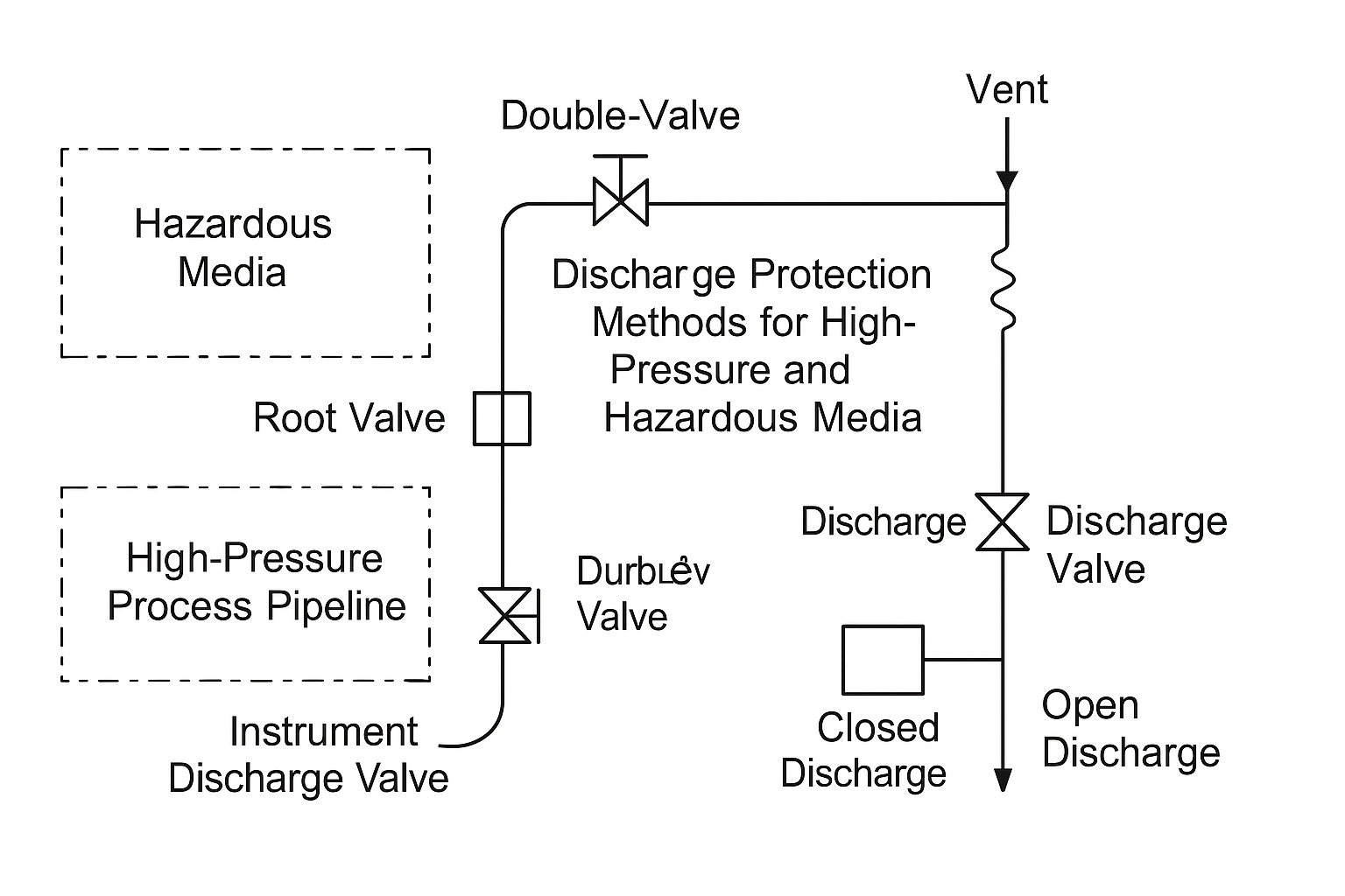
Pressure Containment:
For systems rated ≥ PN160 using dual root valves, instrument discharge valves must also be dual valve type or single valve with cap.
Atmospheric Interfaces: Any discharge port open to atmosphere must be fitted with plugs or protective covers, and stainless steel mesh guards should be used where appropriate.
🔧 Illustration 3: Discharge Protection Methods for High-Pressure and Hazardous Media
4. Compensation and Mechanical Support
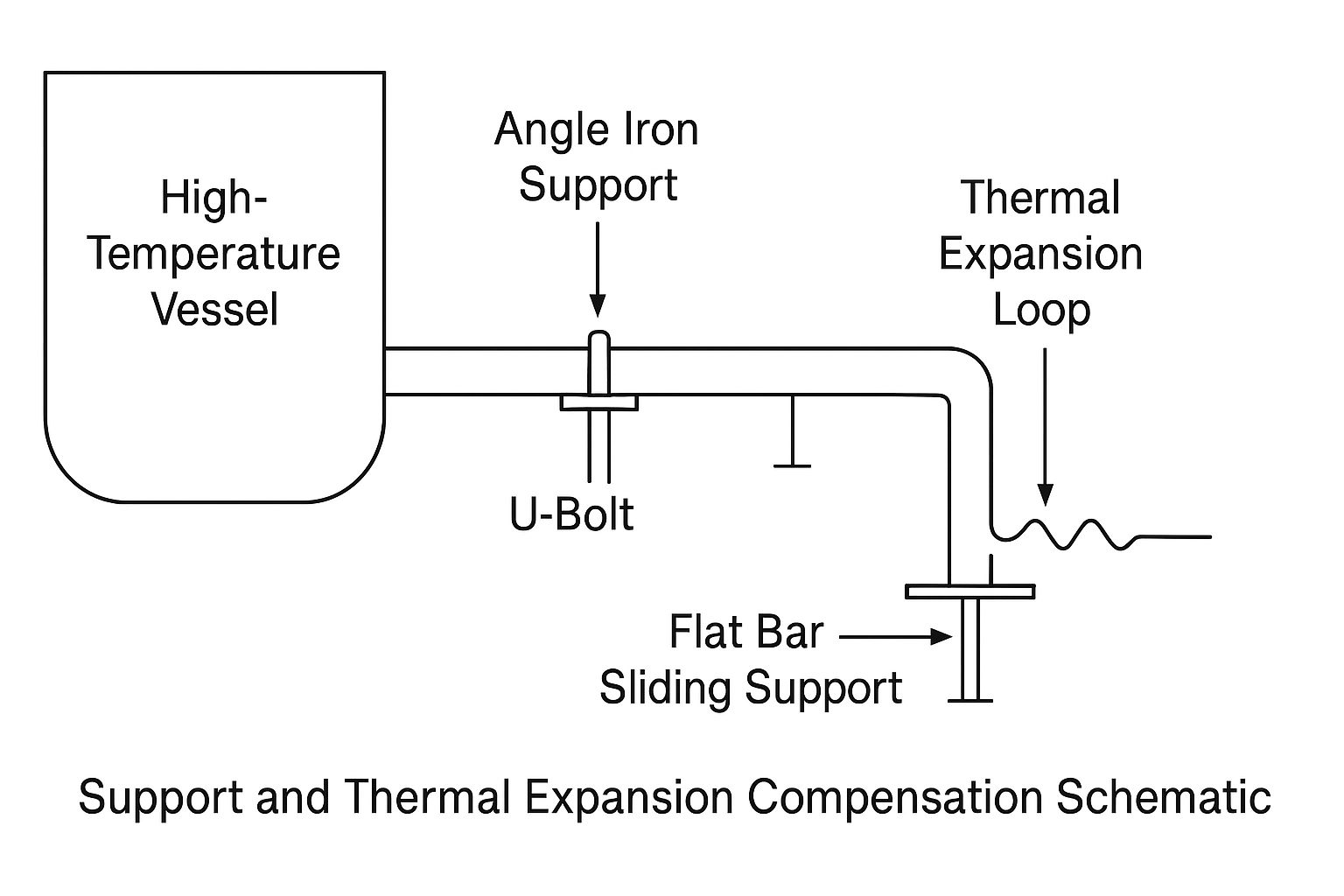
Thermal Expansion: When connected to high-temperature equipment or piping, implement thermal expansion compensation loops or flexible joints.
Support Structures: Use angle iron, flat bars, or U-bolts to secure pipes. Attach supports firmly to walls, frames, or pipe racks.
🔧 Illustration 4: Support and Thermal Expansion Compensation Schematic
5. Instrument Accuracy and Stability Requirements
Differential Pressure Lines: Both positive and negative pressure lines must be installed in areas with the same ambient temperature to prevent measurement drift.
Flexible Connections:
When connecting to glass-type micromanometers, use flexible tubing.
The connection point should be 150–200 mm above the instrument inlet.
Clearance from Structures:
Maintain a minimum clearance of 50 mm between instrument tubing and adjacent surfaces.
For flammable or combustible liquids, the minimum distance from hot surfaces should be ≥ 150 mm, and tubing must not run parallel above such surfaces.
🔧 Illustration 5: Clearances and Flexible Tubing Connection Example
Summary Table: Key Installation Practices
Category
Best Practice
Routing
Avoid heat, corrosion, obstruction, and vibration zones
Slope
1:10 to 1:100 horizontal gradient
Drains & Vents
Add based on phase and position
Pressure Safety
Use dual valves or caps for high-pressure applications
Fixing & Support
Use angle iron, U-bolts, wall/frame/pipe rack mounting
Thermal Management
Apply insulation or heat tracing for critical media
Structural Clearance
≥ 50 mm (general), ≥ 150 mm (flammable fluids near heat)