1. Pre-Installation Checklist
1.1 Environmental Inspection
Ensure there are no strong electromagnetic interference sources nearby, such as VFDs or large motors.
Confirm that the power supply matches the device’s rating (either DC 24V or AC 220V as indicated on the nameplate).
Inspect the inner tank wall. If welding seams or rough surfaces are present, install the sensor at least 0.3 meters away from the tank wall.
1.2 Required Tools and Materials
Shielded cable with cross-section ≥ 0.75 mm²
Waterproof tape
Rubber vibration dampers
Spirit level or laser level for alignment

2. Installation Positioning
2.1 Vertical Mounting Principle
Mount the probe vertically at the center of the tank top, ensuring that the emitting surface is parallel to the liquid surface.
Avoid placing it directly above inlet/outlet ports or agitators.
Blind zone control: Ensure the minimum distance between the maximum liquid level and the probe is greater than the sensor’s blind zone (typically ≥ 0.3 m). If this cannot be achieved, use an extension tube with a diameter ≥ 120 mm.
2.2 Adaptation to Special Containers
Conical Tanks: Install directly above the cone apex for vertical echo reflection.
Domed Tanks: Position the sensor at ½ to ⅔ of the tank top radius to avoid echo distortion from the curved roof.
3. Wiring Specifications
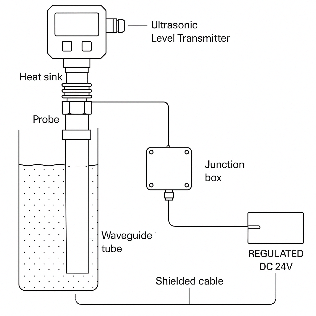
3.1 Four-Wire Connection
Power Supply:
DC 24V: Brown = Positive, Blue = Negative
AC 220V: Use an isolation transformer before connection
Signal Output:
4–20 mA (Black/White wires): Route through a separate shielded metal conduit, away from power lines by at least 20 cm.
3.2 Grounding Requirements
Connect the instrument housing and signal shielding layer to a dedicated grounding electrode.
Ground resistance should be ≤ 4 Ω.
For explosion-proof environments, grounding must meet Ex d standards.

4. Commissioning and Calibration
4.1 Parameter Initialization
Upon startup, configure:
Measuring Range (e.g., 0–10 m)
Sound Velocity Compensation (automatic temperature adjustment)
Output Mode (Linear/Square Root)
4.2 Zero/Span Calibration
Perform zero-point calibration in an empty tank.
Conduct span (full-range) calibration when the liquid level reaches at least 90% of the full scale.
If deviation exceeds 1%, check the sensor alignment.
4.3 Signal Optimization
Use an oscilloscope or built-in self-diagnostic tool to check echo strength (recommended ≥ 80%).
If the echo is weak, consider:
Adjusting probe height
Cleaning the probe surface

5. Handling Special Conditions
| Scenario | Recommended Solution |
|---|---|
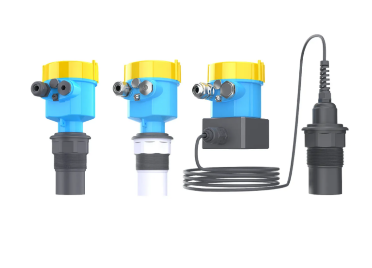
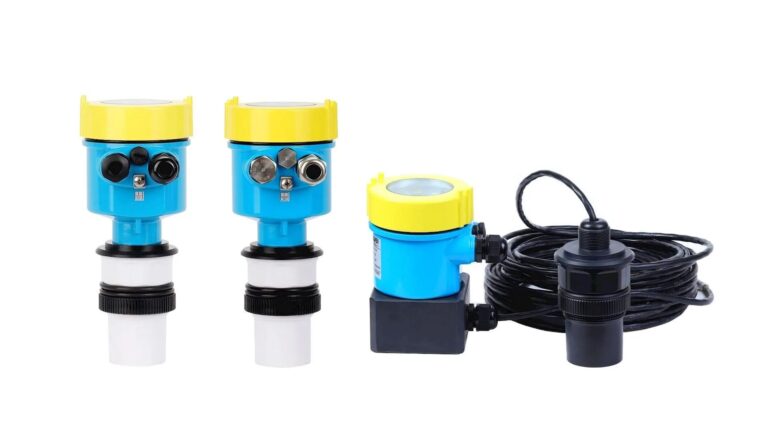
| High-Temperature | Use a split-type design, keep the probe ≤ 15 m from the transmitter, and add heat sinks rated up to 150°C. |
| Foam/Steam Interference | Use high-frequency probes (80 kHz), lower the sensitivity threshold, and install a guiding pipe (diameter ≥ 100 mm). |
| Outdoor Installation | Add a sunshade, waterproof junction box, and seal cable entries with silicone to achieve IP68 protection. |
6. Acceptance and Performance Standards
6.1 Measurement Accuracy
Static Liquid Level: Measurement error ≤ ±0.3%
Dynamic Level Fluctuations: Error ≤ ±1%
6.2 Stability Test
Continuous operation for 72 hours
Signal drift ≤ 0.1% FS
Relay switching error ≤ 0.5%

✅ Conclusion
Following this comprehensive installation guide will ensure reliable operation of four-wire ultrasonic level transmitters even in complex industrial environments. It supports high precision, anti-interference performance, explosion protection, and long-term stability.
