Vortex flow meters, based on the Kármán vortex street principle, are widely used for measuring the flow of industrial fluids—gas, liquid, and steam. Proper installation and routine maintenance are crucial to ensuring their measurement accuracy and prolonging operational lifespan. This document outlines detailed guidelines for installation, daily inspection, and maintenance.
1. Installation Guidelines
1.1 Pre-Installation Preparation
Instrument Check: Verify the flow meter specifications (e.g., diameter, pressure rating, medium temperature, explosion-proof class) match the process requirements. Inspect the instrument for physical damage and ensure all accessories (flanges, bolts, gaskets, converter) are complete.
Pipeline Check: Ensure the pipeline is clean, free from rust or welding slag. Inner diameter should match the meter size to avoid eccentric or reduced-bore installation. Flush the pipeline if needed.
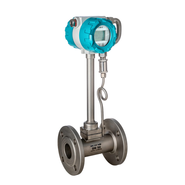
Figure 1: Proper alignment and flange connection schematic
If upstream has disturbance sources (elbows, valves, reducers): ≥20D upstream + 5D downstream
Avoid Harsh Environments:
Keep away from vibration sources (e.g., pumps), heat sources, or strong electromagnetic fields (e.g., inverters).
Ambient temp: -20°C to +60°C; Humidity ≤85% RH
Installation Orientation:
Horizontal: Sensor axis parallel to the ground, pipe fully filled.
Vertical: Medium should flow from bottom to top (recommended for liquids).
Inclined: For steam or gas, ensure slope supports condensate drainage.
Figure 2: Installation direction and orientation scenarios
1.3 Installation Procedure
Flange Connection: Ensure coaxial flange alignment; tighten bolts evenly. Gasket must not intrude into the flow path.
Sensor-Converter Wiring: Use shielded signal cables through metal conduits. Keep away from power cables. Ensure correct polarity and grounding resistance ≤10Ω.
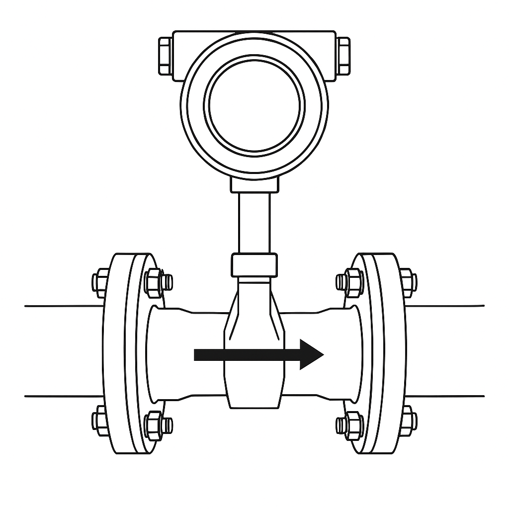
Flow Direction: Confirm arrow on housing matches actual flow direction.
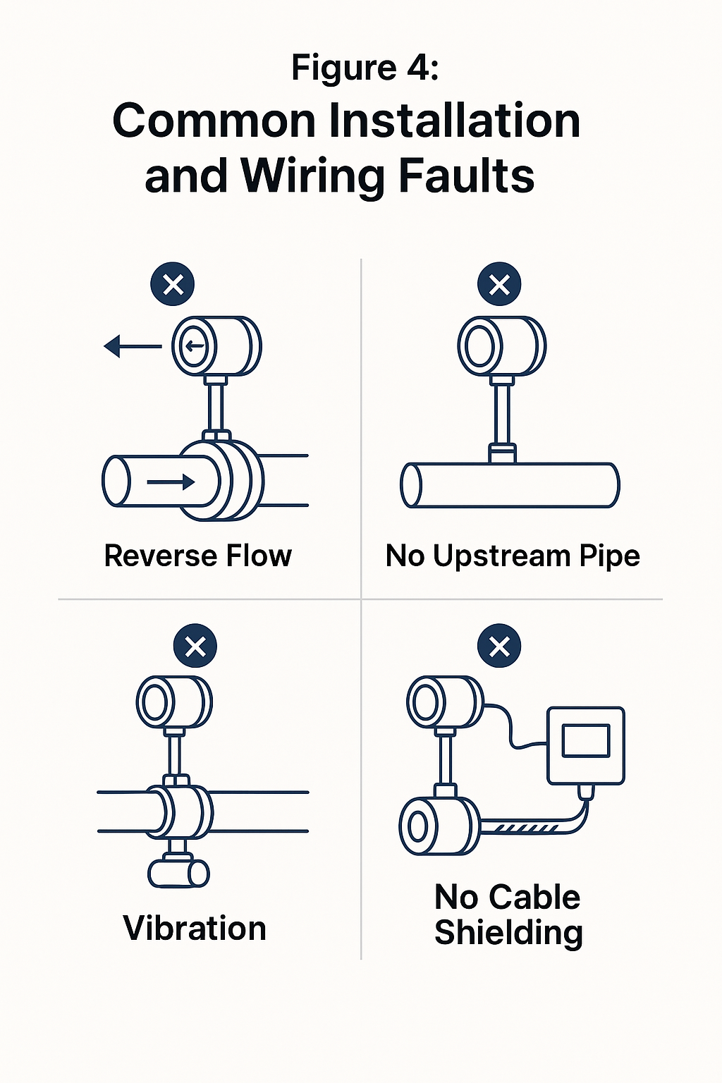
Figure 4: Common installation and wiring faults (visuals)
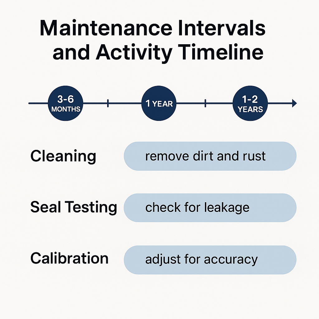
4. Maintenance Records & Log
Maintain a log including:
Dates and descriptions of inspection, cleaning, calibration
Any abnormalities and corrective actions taken
Component replacements and verification records
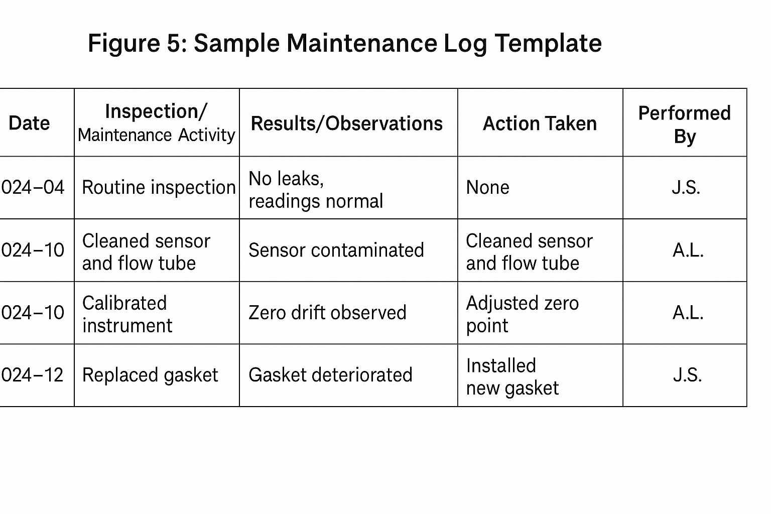
Figure 5: Sample maintenance log template
5. Safety Precautions
During installation/repair: Shut off process media, depressurize, and disconnect power. Explosion-proof tools are mandatory in hazardous zones. Never open the housing while powered.
At height: Use safety harness, ensure supervised operation.
Chemical media: Wear protective gear to avoid skin contact or inhalation of vapors.
6. Long-Term Shutdown Care
If the meter is out of service >3 months:
Drain the pipeline; store the sensor in a dry, non-corrosive atmosphere.
Power off the converter, cover with dust-proof hood.
Perform full inspection, calibration, and leak test before reuse.
✅ Conclusion
Through proper installation and scheduled maintenance, the performance and reliability of vortex flow meters can be greatly enhanced. In the event of complex failures (e.g., internal circuit faults or damaged probes), contact the manufacturer’s technical support—unauthorized disassembly is not recommended.