Temperature transmitters convert signals from temperature sensors such as thermocouples and RTDs into standard analog signals (e.g., 4–20 mA or 0–10 V) through processing circuits including voltage regulation, filtering, amplification, linearization, V/I conversion, and protection. They are widely used in industrial process control for accurate temperature measurement.
1. Overview and Structure
A typical temperature transmitter consists of:
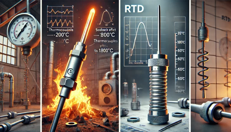
Sensing element (e.g., thermocouple or RTD)
Signal processing and conversion unit
Optional: Display interface or fieldbus communication module
2. Inspection and Performance Testing
2.1 Routine Inspection Items
Routine checks should include visual inspection, electrical continuity, label verification, and connector integrity.
2.2 Periodic Testing
Performance and insulation tests should be conducted at least annually.
Insulation Test: Disconnect wiring and measure resistance between terminal and housing using a 500 V megohmmeter.
Metrological Verification:
With Sensor: Place sensing element into a temperature calibrator and verify output response.
Without Sensor: Disconnect sensor and input standardized resistance or voltage using calibration instruments.
2.3 Calibration Guidelines
Point Selection: At least 5 calibration points evenly distributed across the full scale (including min, max, and 50%).
Pre-adjustment: Calibrate lower and upper range output using standard signal source.
Procedure:
With Sensor: Measure from lowest to highest temperature after stabilization.
Without Sensor: Input electrical signals corresponding to temperatures and record output.
Data Precision: Round data so that rounding error is < 1/10 to 1/20 of max allowable error.
3. Calibration and Adjustment
If the transmitter exhibits zero drift, range deviation, or excessive measurement error, calibration is needed.
3.1 Tools Required
HART communicator
Digital readout
Simulated RTD or thermocouple source
3.2 Adjustment Procedures
Sensor Trim: Match process variable (PV) displayed by communicator with standard input.
Analog Output Trim: Compare analog output (AO) with readout device and adjust accordingly.
4. Installation and Operation
Ambient temperature range: –25°C to +70°C
Avoid vibration; insertion depth: ½ to ⅔ of pipe diameter
Wiring: Follow instructions for 2-wire, 3-wire, or 4-wire configurations
For explosion-proof or intrinsic safety applications, ensure correct safety barrier is used.
5. Maintenance and Troubleshooting
Keep units clean and sealed
Do not dismantle under power
Inspect regularly for calibration, drift, and output anomalies