Abstract
The IMA8-EZ02 paperless recorder is a modern data acquisition and visualization platform for process industries. It supports multi-signal inputs (current, voltage, thermocouples, RTDs, resistance, frequency), real-time and historical trending, and secure solid-state storage with USB export. Optional 4–20 mA analog outputs, 24 VDC transmitter power, and serial communications make it easy to integrate with PLC/DCS systems in power, chemical, water treatment, and laboratory environments.
1) Key Features at a Glance
Channels: 1–40, with scan period down to 1 s for time-critical loops.
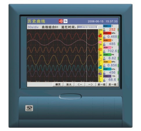
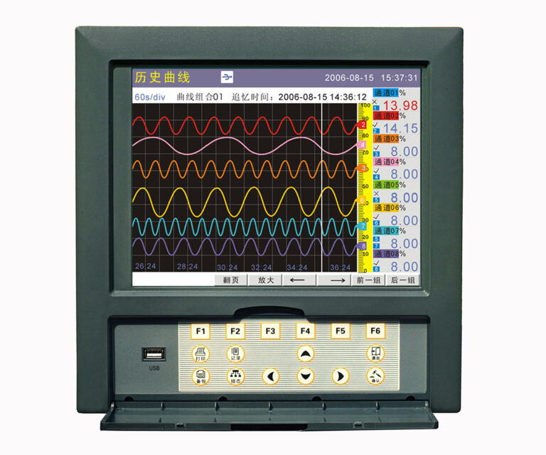
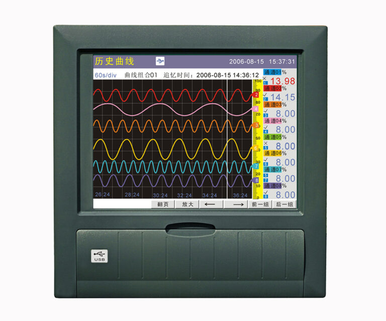
Display: 10.4″ TFT color LCD (640×480); numeric, bar, real-time trend, history, alarms, and reports.
Storage & logging: Internal flash + USB drive (FAT32, up to 32 GB); logging interval 1 s–4 min (configurable).
Alarms: Per-channel HH/H/L/LL with hysteresis; optional relay outputs for horn/interlocks.
Outputs (options): Up to 8× 4–20 mA analog outputs (≤750 Ω load); 24 VDC power for field transmitters (up to 8 loops, each ≤60 mA).
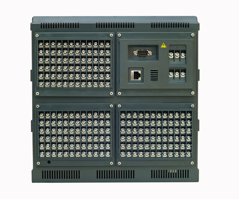
Communications: RS-232C / RS-485 (Modbus-friendly), for SCADA or DCS integration.
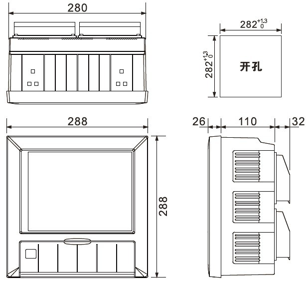
Form factor: Panel-mount recorder with compact depth; accessory DIN-rail modules available.
2) Input Signal Coverage & Wiring Notes
Supported signal families
Current: 0/4–20 mA (active or passive); scaling to engineering units.
Voltage: Typical low-level ranges (e.g., 0–5 V, 1–5 V, 0–10 V).
Thermocouples (TC): K, J, T, E, N, S, R, B commonly used in process temperature.
RTDs: Pt100/PT1000 (2/3/4-wire), Cu series where applicable.
Resistance/Frequency: For sensors like load cells with conditioners, turbine flow pickups, etc.
Wiring best practices
4–20 mA: Use twisted-pair; if powering from the recorder’s 24 VDC, check loop burden and keep total ≤60 mA per loop.
RTD 3-wire: Keep lead lengths equal to minimize error; use copper of the same gauge; enable lead compensation.
Thermocouples: Use matching TC extension cable; terminate at recorder’s CJC terminals; avoid mixed metals at junctions.
Shielding/grounding: Ground shields at one end (usually at the recorder cabinet). Maintain a clean instrument ground.
3) Display & Analysis Tools
Multi-view HMI: Numeric, bar graph, and multi-pen trends for quick correlation across channels.
History browser: Cursor readout, zoom, and export to USB for offline analysis.
Batch/lot labeling: Tag data with batch names and timestamps for audits.
Reports: Daily/weekly/monthly summaries with min/max/avg, counts of alarms, and run-time statistics.
4) Alarms, Logic, and Outputs
Per-channel 4-point alarms (HH/H/L/LL) with hysteresis to prevent chatter.
Latching & ACK options for operators; audible horn and relay tie-ins.
Relay outputs (option) for annunciation or interlocks (consult your I/O card rating).
Analog outputs (option) mirror process variables to PLC/DCS analog input cards (0/4–20 mA).
5) Data Storage, File Handling & Traceability
Logging interval configurable from 1 s to 4 min per your process dynamics.
Internal memory + USB allows high-density, long-term recording.
File export (USB, FAT32) compatible with spreadsheet tools; retain raw + metadata (channel tags, engineering units, timestamps).
Retention planning: Size your interval and channel count to meet audit windows (e.g., 30/90/365 days).
Audit trail: Use user accounts and batch tags to maintain traceability.
6) Communications & System Integration
Serial RS-232C/RS-485 for Modbus-style integration with SCADA/DCS/PLC.
Typical settings: baud 9.6k–38.4k, 8N1; device address per station (confirm actual defaults in the unit).
Use cases:
SCADA polls real-time values and alarm states.
DCS writes setpoints to recorder’s analog outputs (if enabled) for retransmission.
Historian pulls archived data from USB for central storage.
7) Commissioning Checklist (Step-by-Step)
Mount & clearances: Panel-cutout, ventilation, and access for USB stick.
Power & ground: Verify mains or 24 VDC, earth ground, and shield terminations.
I/O mapping: Name channels (Tag, ENG units), assign input types, set ranges and decimal places.
Scaling & linearization: Apply sensor curves where needed (TC type, RTD coefficients, custom scaling).
Logging plan: Set interval (e.g., 1 s for fast loops; 5–10 s for slow variables).
Alarms: Define HH/H/L/LL setpoints, deadbands, latching, relay ties.
Security: Create user roles/passwords; enable config lock if the site requires.
Timebase: Set clock/timezone; if multiple recorders exist, standardize time to avoid drift.
Communications: Set serial parameters; test with master (SCADA/PLC).
Dry run: Simulate inputs; verify trends, alarms, reports, and USB export.
8) Installation & Environmental Considerations
Cabinet environment: Keep away from high-EMI devices (VFDs, contactors). If unavoidable, add line filters and separate routing.
Ambient: Use within the unit’s specified operating temperature/humidity range; avoid condensation.
Field wiring: Separate low-signal (TC/RTD/mA) from power lines; cross at 90° if necessary.
Surge/lighting: Consider surge protection on outdoor runs.
9) Maintenance & Calibration
Annual check: Verify input accuracy with a traceable calibrator (mA, TC, RTD sims).
Channel health: Use diagnostics to spot open TC, broken RTD lead, or loop faults.
Firmware/config backup: Keep a copy of the configuration file; periodically back up logs to USB.
Display/HMI: Clean gently (no solvents) to preserve the TFT surface.
10) Troubleshooting Quick Guide
| Symptom | Likely Cause | Quick Fix |
|---|---|---|
| No signal on mA input | Open loop, wrong input type, wiring swapped | Check 24 V loop power, input range, polarity |
| TC reading drifts | Mixed metals, poor shielding, CJC disabled | Use correct TC cable, enable CJC, ground shield one-end |
| RTD unstable | Unequal leads, 2-wire used on long runs | Switch to 3-wire, equalize lead lengths |
| Trends look “steppy” | Log interval too long | Reduce to 1–2 s for fast-changing processes |
| Alarms chatter | No hysteresis configured | Add adequate deadband (e.g., 0.5–1% span) |
| PLC comm timeouts | Address/baud mismatch, long trunk | Match serial settings; add repeaters/termination |
11) Typical Industry Use Cases
Power generation: Drum level trends, superheater temperature, turbine bearing temperature, vibration envelope.
Chemicals: Reactor temperature profiles, pH and conductivity tracking, pressure and flow interlocks.
Water & wastewater: Filtration ΔP, flow totals, turbidity trends for compliance.
Lab & R&D: Multi-sensor experiments with batch tagging and high-rate logging.
12) FAQs (Buyer-Friendly)
Q1: Can I mirror a channel to my PLC?
Yes—use the optional 4–20 mA analog output to retransmit a measured variable to a PLC/DCS AI card (ensure ≤750 Ω load).
Q2: How much data can I store?
With internal flash and USB up to 32 GB, retention depends on channel count and log interval. As a rule of thumb, slower intervals and selective channel logging extend retention for audits.
Q3: Do I need external power for my 2-wire transmitters?
Not necessarily. The recorder offers 24 VDC loop power (option). Check loop current; keep ≤60 mA per loop.
Q4: Is it Modbus-compatible?
It provides serial ports (RS-232C/RS-485) suitable for Modbus-style polling by SCADA or PLC masters. Configure address and baud to match your system.
Q5: Can it generate compliance reports automatically?
Yes—use built-in daily/weekly/monthly reports and export data via USB for archiving.