Introduction
Coils are everywhere—from motors and solenoids to transformers, relays, and magnetic sensors. While turn count, wire gauge, and core material usually get the spotlight, winding direction (clockwise vs. counterclockwise) is just as critical. It determines the polarity of the magnetic field, the phase relationship between coupled windings, and whether two coils add or cancel each other’s fields. This article explains the physics, shows how direction interacts with current, and offers practical checks you can use in the workshop or on the production line.
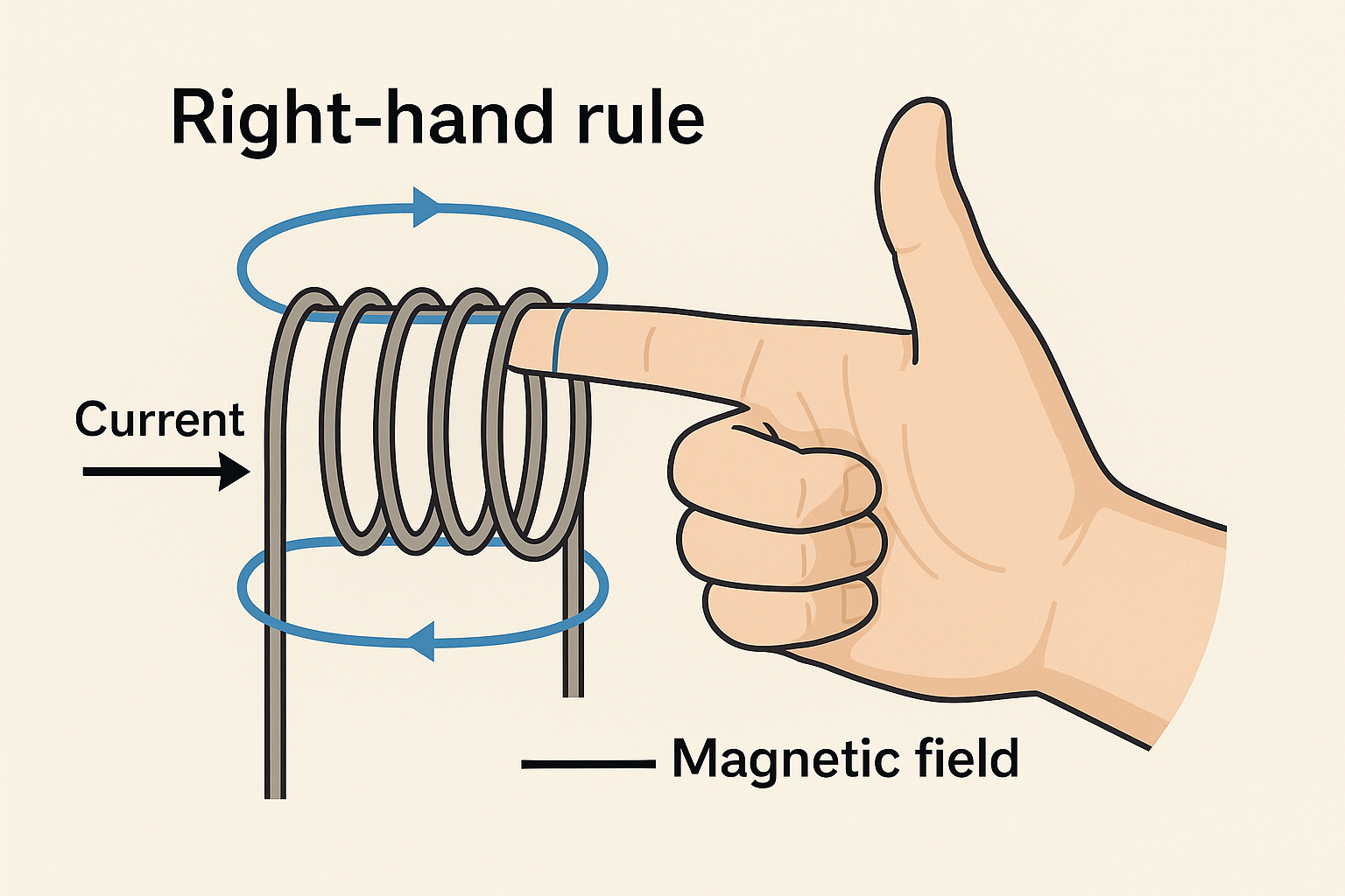
1) Field Direction in One Picture: The Right-Hand Rule
Right-hand rule for coils: Curl the fingers of your right hand in the direction of conduction path around the coil; your thumb points along the coil’s axial magnetic field (the “north” side).
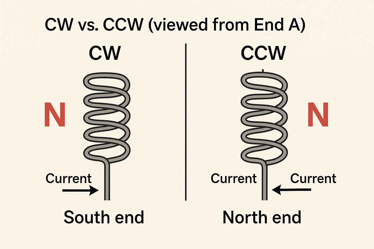
Define the viewpoint: Always state “viewed from end A” when calling a winding CW (clockwise) or CCW (counterclockwise). Without a reference end, CW/CCW is ambiguous.
Mathematically, a coil’s magnetic dipole moment is
m=NIA
where N is turns, I is current, and A is the area vector set by winding sense via the right-hand rule. Flip the winding sense or the current, and m flips.
For a long solenoid (air core), the axial field magnitude is approximately
B≈μ0nI
with n=N/L. The sign (north/south end) is set by winding direction together with current direction.
2) Winding Sense vs. Current Direction
Think in pairs:
Same current, opposite winding directions → opposite field polarity.
Same winding direction, reversed current → opposite field polarity.
Reverse both winding direction and current → field polarity unchanged.
This explains why coils sometimes still “work” after both leads were swapped and the bobbin was flipped: two errors canceled.
3) Phasing and the Dot Convention (Coupled Coils)
For transformers and any magnetically coupled pair, the dot convention marks the “in-phase” ends.
If current enters the dotted end of the primary, an instantaneously positive voltage appears at the dotted end of the secondary (for positive dI/dt).
Series-aiding connection of two identical inductors: make the current enter both dotted ends simultaneously (their induced voltages and fields add).
Series-opposing: arrange so that current enters the dotted end of one coil and the undotted end of the other (fields partially or fully cancel).
Practical result: winding direction determines where the dot belongs; getting it wrong flips the measured phase and can cause cancellations or 180° phase errors in multiwinding systems.
4) Application Playbook
4.1 Motors (DC, BLDC, AC)
Stator/rotor coils must be wound and connected so that magnetic poles appear in the intended sequence.
A wrong winding sense on one phase can reduce torque, create cogging/vibration, or prevent startup.
In BLDC stators, phase groups must produce N-S-N-S in space with proper electrical phase shift; one reversed phase behaves like an opposing brake.
4.2 Transformers & Multi-Winding Inductors
Primary/secondary winding sense sets the output polarity at any instant and the phase relationship.
Parallel secondaries must have the same instantaneous polarity (same dot ends tied together); otherwise, they circulate current and overheat.
Series windings can be added aiding (voltage up) or opposing (voltage down) by observing dot ends.
4.3 Solenoids, Relays, and Valves
Winding sense with a given current defines which end is north, thus the pull direction on an armature.
If a design expects “north toward plunger,” flipping sense without flipping current causes weaker pull or mechanical misbehavior.
4.4 Magnetic Sensors (Hall, AMR/GMR) & Calibration Coils
Sensor datasheets specify a sensitive axis and polarity. Coil winding must generate the correct field sign relative to that axis.
Helmholtz (series-aiding) and anti-Helmholtz (opposing) coil pairs rely entirely on winding sense to create uniform fields (Helmholtz) or well-defined gradients (anti-Helmholtz).
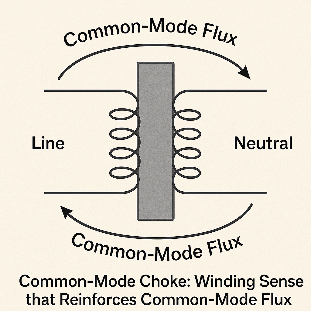
4.5 EMI & Power Filtering (Chokes)
Common-mode chokes: two windings on a shared core, wound so that line and neutral common-mode currents produce reinforcing flux (high impedance). Differential currents largely cancel.
Differential-mode inductors: windings or sections arranged so differential current sees added inductance; reversing one section can kill the intended impedance.
5) Production & QA: How to Specify and Verify
5.1 Clear Specifications
Reference end: “CW as viewed from terminal end A.”
Lead naming: mark Start (S) and Finish (F) on drawings and bobbins; map S↔dot or F↔dot consistently.
Dot marks on schematics and physical parts (paint dot, notch, laser mark).
Polarity tables in the datasheet: e.g., “Current from S→F produces north at End A.”
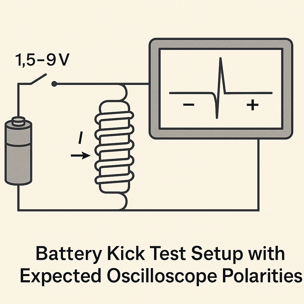
5.2 Quick Bench Tests
Compass test: drive DC through the coil; note which end deflects a compass north.
Battery “kick” + oscilloscope: momentarily connect a 1.5–9 V source through a switch to the primary; watch induced pulse polarity on the secondary. The first pulse sign reveals the dot end.
Hall probe test: apply steady current and read the sign with a Hall sensor aligned to the coil axis.
Series-check for aiding/opposing: put two windings in series, drive with AC, and measure inductance L. Higher L → aiding; lower L → opposing.
5.3 Documentation & Traceability
Print the winding sense and dot on labels and test reports.
Photograph the coil from the reference end for the traveler pack.
Record measured polarity and inductance (aiding/opposing) in the QA sheet.
6) Common Pitfalls (and How to Avoid Them)
Ambiguous CW/CCW: Always state the viewpoint; otherwise CW becomes CCW when seen from the opposite end.
Bobbin flipped during assembly: Mark both the core side and the terminal side; flipping invalidates the drawing’s sense.
Paralleling out-of-phase windings: Causes hot copper and humming transformers—use the dot test first.
Series sections mis-phased in high-current inductors: Inductance falls, ripple rises, core saturates earlier.
Sensor axes ignored: Hall/AMR devices read “negative” or saturate because the field is applied with the wrong sign.
7) Worked Example
A solenoid has N=500 turns, length L=50mm, air core, current I=0.20A.
n=N/L=0.05500=10,000 turns/m,B≈μ0nI≈(4π×10−7)×10,000×0.20≈2.51×10−3 T
If viewed from End A the winding is CW and current flows such that your right-hand fingers curl CW, End A is north. Reverse either winding sense or current and End A becomes south; reverse both and End A remains north.
8) Design Checklist
Define reference end and winding sense on the drawing.
Map S/F leads to dot marks and specify polarity table.
For multiwinding parts, add a phasing diagram (dots on each winding).
Specify the test method (battery kick + scope, or Hall probe).
For paired coils (Helmholtz/chokes), state series-aiding/opposing requirement explicitly.
Lock photos of a golden sample into the traveler.
9) Key Takeaways
Winding direction sets the sign of a coil’s magnetic field for a given current.
In coupled windings, dot convention formalizes this sign, controlling phase and whether windings add or cancel.
Many failures—weak torque, hot transformers, noisy filters—trace back to mis-phased or reversed windings.
Clear drawings, unambiguous labels, and one-minute polarity tests eliminate 90% of related issues.