Troubleshooting ground faults in emergency shutdown signal cables requires a structured approach to ensure efficiency and safety. This process can be broken down into several key stages: preparation, step-by-step cable inspection, the use of diagnostic tools, and dealing with special cases. Below is a detailed explanation of each step, followed by important precautions to follow during troubleshooting.
1. Preparation Before Troubleshooting
Proper preparation is essential to ensure the troubleshooting process is efficient and safe. Follow these steps:
Gather Necessary Documentation: Before starting, collect detailed information about the cable layout, length, type, and specifications. Additionally, review relevant design drawings and installation records. Be sure to understand the cable’s operational history, including previous faults, fault locations, and how they were addressed.
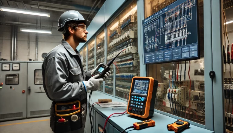
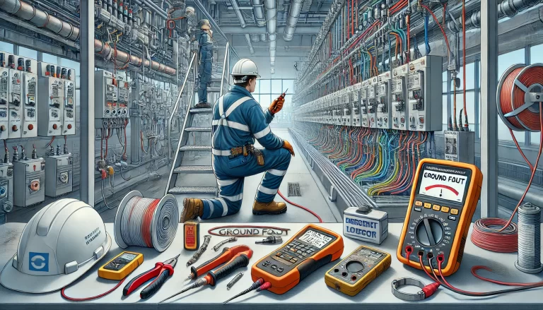
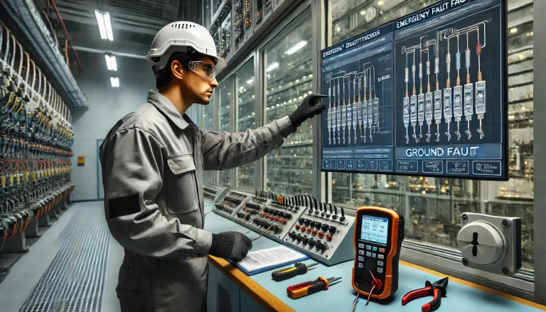
Prepare Tools and Instruments: Have all required tools and diagnostic instruments on hand, such as an insulation resistance tester, multimeter, cable fault locator, and megohmmeter. Basic electrical tools like pliers, screwdrivers, and wrenches should also be ready for use.
Safety Precautions: Prior to beginning the troubleshooting process, ensure that all equipment is de-energized. Implement necessary safety protocols, including wearing insulated gloves, helmets, and using lockout/tagout devices.

2. Step-by-Step Cable Inspection
Conducting a thorough inspection of the cable is a crucial first step in identifying the fault. The inspection can be done in the following phases:
Visual Inspection: Inspect the cable for visible damage. Look for signs such as cuts, abrasions, aging, or scorch marks. Pay special attention to areas like cable joints, bends, and places where the cable passes through buildings or pipes, as these are more prone to damage.
Segmentation and Isolation: If the cable spans a large area, divide it into manageable sections. Disconnect the cable at intermediate connection points or use switchgear to isolate sections. Use an insulation resistance tester to measure each segment. A significant drop in insulation resistance in a particular section indicates the fault is likely located there.
Branch Line Testing: For cables with multiple branches, each branch should be tested individually. Disconnect the branches from the main cable and test their insulation resistance separately, narrowing down the fault location progressively.
3. Using Diagnostic Instruments for Accurate Detection
Certain faults may be difficult to identify using visual inspection or basic resistance tests. In these cases, specialized instruments can provide valuable insights.
Insulation Resistance Testing: The insulation resistance test is the primary method for detecting ground faults in cables. Ensure that the cable is de-energized before performing the test. Measure the insulation resistance between each conductor and ground. A resistance value close to zero or significantly lower than the normal range indicates a ground fault.
Cable Fault Locator: When traditional methods fail, a cable fault locator can help pinpoint the fault. These devices emit pulse signals and analyze their reflections to locate the fault. Common techniques include pulse reflection and step voltage methods. Choose the appropriate method based on the cable type and fault condition.
Ground Fault Current Measurement: Use a clamp meter to measure the ground fault current in the cable. Under normal conditions, the ground fault current should be minimal. If the current is higher than expected, it indicates a fault. Moving the clamp meter along the cable’s path will allow you to monitor current fluctuations and identify areas with significantly higher currents, which can help locate the fault.

4. Troubleshooting in Special Situations
Some cable installations present unique challenges, such as underground cables or cables passing through pipes. Special techniques are necessary for these cases.
Hidden Cable Inspection: For cables buried underground or enclosed in conduits, it may be difficult to visually inspect them. In these situations, use a cable locator to map the cable’s route. Once located, the area of concern can be accessed through excavation or drilling to perform further testing.
Environmental Considerations: The environment where the cable is installed can significantly affect its performance and vulnerability to faults. For example, cables in humid environments may suffer from insulation degradation, while those exposed to corrosive gases may experience external damage. Identify areas most likely affected by these environmental factors and prioritize them during the inspection.
Historical Fault Review: Review past fault records to determine if there are any recurring issues in specific locations. If a fault has occurred multiple times in the same area, this region should be treated as a high-risk zone and warrant further investigation.
5. Important Considerations During Troubleshooting
When troubleshooting ground faults, several considerations must be taken into account to ensure both safety and effective operation.
Safety Considerations:
De-Energize the System: Always verify that the equipment and cable system are completely de-energized before starting the troubleshooting process. Follow lockout/tagout procedures and use safety signage, such as “High Voltage – Do Not Enter,” to alert personnel to potential hazards.
Eliminate Induced Voltage: Even after de-energizing the cable, electromagnetic induction from nearby live circuits may still create a residual voltage. Use a grounding rod to discharge any induced voltage before handling the cable.
Environmental Hazards: When inspecting cables located in confined spaces like tunnels or cable trenches, be aware of potential hazards such as low oxygen levels or the presence of toxic gases. Ensure proper ventilation and use gas detection equipment to monitor air quality before entering potentially hazardous areas.

Operational Considerations:
Instrument Handling: Familiarize yourself with the proper use and operation of all diagnostic instruments. Ensure correct settings on tools like insulation resistance testers and clamp meters to avoid errors.
Avoid Accidental Damage: Be cautious to avoid further damage to the cable during the inspection. For example, when digging or drilling to access buried cables, take care not to cut or puncture the insulation.
Documentation and Analysis:
Accurate Record Keeping: Document all readings, measurements, and observations made during the troubleshooting process. These records will assist in fault analysis and provide a reference for future maintenance.
Comprehensive Analysis: When evaluating the fault, don’t rely solely on one testing method. Instead, analyze multiple data points, including visual inspection, resistance tests, current measurements, and environmental factors, to identify the exact cause of the fault.
Collaborate and Communicate: If difficulties arise or the fault is difficult to locate, involve other professionals, such as electrical engineers or maintenance personnel, to brainstorm potential solutions and ensure a more accurate diagnosis.

Conclusion
By following these steps and utilizing the right tools and techniques, troubleshooting ground faults in emergency shutdown signal cables can be completed swiftly and efficiently. Always ensure safety precautions are followed and thorough documentation is maintained. This approach not only helps in quickly pinpointing faults but also minimizes downtime and improves the reliability of the electrical system.
