In the instrumentation industry, theoretical knowledge is like a wrench in your hand—seemingly simple, but essential when it’s needed. Whether you’re preparing for a certification exam or just looking to build a solid foundation for daily work, understanding circuit diagrams, sensor principles, and troubleshooting logic is crucial. This series will keep updating, providing both theoretical insights and practical skills. Even with just a few minutes of spare time, you can build a solid foundation. Let’s improve our theoretical understanding together, so we can work more confidently!
1. Measuring Voltage in Transmitter Circuits
Figure 1: Measuring Transmitter Circuit Voltage
In Figure 1, we have the measurement circuit for a transmitter. Using a multimeter on the DC voltage setting, measure the voltage across terminals a-b and c-d to check if the transmitter’s measurement circuit is functioning properly.
If the voltage across a-b is greater than 24V, there may be an issue with the power supply. Check the 24V power supply.
If the voltage across a-b is around 24V, the transmitter is working properly. Meanwhile, the voltage across c-d should range between 1V and 5V, indicating that the transmitter is outputting current and functioning correctly.
If a-b shows a voltage slightly above 24V, but c-d is 0V, the transmitter could be faulty.
If a-b shows 0V, this could be due to a 24V power failure, an open circuit, or reversed wiring. In this case, c-d would likely show a voltage of ≤0V.
If a-b shows a low or 0V reading, it may indicate a short circuit. If the current is high and c-d voltage is ≥5V, the transmitter itself may have a short circuit. If c-d is low or 0V, the issue could be with the wiring, and the fault likely lies before the DCS input board.
2. Measuring UPS Battery Voltage
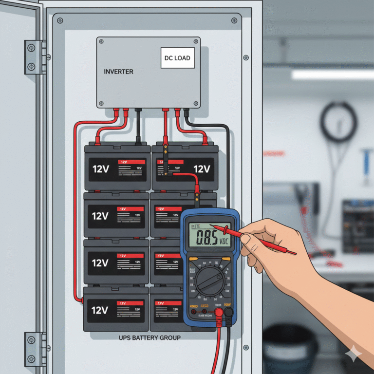
UPS batteries must be replaced regularly as part of preventive maintenance. Measuring the total voltage of the battery group helps determine whether the batteries are functioning properly. Some batteries may fail prematurely and need to be replaced. In a loaded state, as shown in Figure 2, measure the total battery voltage to identify any failed batteries.
Figure 2: Identifying Failed Batteries in a UPS Battery Bank
When the total battery voltage is lower than expected, it may indicate a failed battery. Measure each battery’s voltage to identify the faulty one. A failing battery will show a lower voltage or may even read zero. Some failed batteries may also have reversed polarity, which should be replaced.
3. Measuring Thermoelectric Voltage in Thermocouples
Thermoelectric voltage in thermocouples can be measured using a digital multimeter. The typical range for the mV setting on a digital multimeter is 200mV or 400mV, with a resolution of 0.1mV. If the measured voltage is less than 2mV, measurement errors may increase. For precious metal thermocouples, the thermoelectric voltage is small, leading to higher measurement error, so it’s best to use a DC potentiometer for more accurate readings.
To check the type of thermocouple or compensation wire, especially when the identification is unclear, follow these steps:
Place the hot end of the thermocouple or compensation wire into boiling water (around 100°C) or heated water (around 80°C).
Measure the thermoelectric voltage at the cold end using a digital multimeter in DC mV mode.
Add the measured mV value to the room temperature corresponding mV value to get the total mV value.
Compare this value with thermocouple tables to determine the type of thermocouple or compensation wire.
If the displayed polarity is positive, the red probe is connected to the positive side, and the black probe to the negative side. If negative, the polarity is reversed.

4. Voltage Measurement Precautions
For analog multimeters, always choose a range that keeps the needle near the full scale for more accurate readings. If the voltage is unknown, start with a higher range and adjust accordingly.
When measuring DC voltage with an analog meter, connect the red probe to the “+” and the black probe to “-” to avoid damage from reverse polarity. If the polarity is unknown, switch to a larger range and briefly touch the probes to the measurement points. Observe the needle direction to determine correct polarity.
Digital multimeters typically have automatic polarity reversal, so there’s no need to worry about polarity when measuring DC voltage.
If you mistakenly use the AC voltage setting to measure DC voltage (or vice versa), the display will show an overflow symbol.
When measuring AC voltage with a digital multimeter, connect the black probe to the common ground (COM) or the lower potential side of the voltage, or the signal source’s common terminal, to reduce measurement error.
For high impedance signals (greater than 10MΩ), the digital multimeter’s input resistance can affect measurements. Consider the bypass effect of input resistance when measuring such signals.