In the field of instrumentation, theoretical knowledge is like the wrench in your hand—it may seem unimportant, but when it’s needed, it plays a critical role. Whether you’re preparing for an entry-level certification or want to solidify your foundation in practical work, topics like circuit diagrams, sensor principles, and troubleshooting techniques are crucial. This series will be updated continuously, providing both theoretical and practical insights. Even a few minutes of study here and there can gradually build solid expertise. Let’s strengthen our theoretical foundation to enhance our work confidence!
1. Inspection of Resistance Temperature Detector (RTD) Three-Wire Circuit
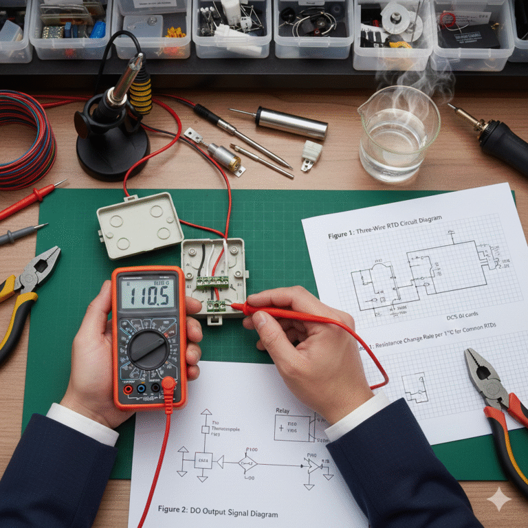
The three-wire RTD measurement circuit is commonly used in temperature measurement. By using a multimeter on the resistance setting, you can measure the resistance across different points to check if the circuit is working correctly.
Figure 1: Three-Wire RTD Circuit Diagram
In the RTD junction box, disconnect the three connecting wires and measure the resistance of the RTD element. For a Pt100 RTD at 25°C, the resistance between wires a-b or a-c should be around 110Ω, while the resistance between b-c should be nearly zero, indicating the RTD is functioning properly.
If the resistance between a-b or a-c is below 100Ω, the RTD might have a local short-circuit fault. If the resistance is infinite, the RTD element could be open-circuited.
If the resistance at the terminals is measured and found to be 120Ω (with 5Ω resistance for each wire), the three-wire connection is correct. However, ensure the connection at the DCS AI cards (A1, B1, C1) is disconnected before measurement. By measuring the RTD’s resistance on-site, you can also verify if the temperature readings are accurate by calculating the temperature based on the resistance values.
| Table 1: Resistance Change Rate per 1°C for Common RTDs |
|---|
| RTD Element |
| Pt100 |
| Pt100 |
| Cu50 |
For example, if an RTD measures 162Ω at the a-b terminals, the estimated temperature is:
(162 – 100) / 0.385 = 161°C.
If the resistance at the A-B or A-C terminals is infinite, this may indicate an open circuit between the wire and the RTD element. If the resistance at B-C is unusually high, it might point to a faulty connection at the B-C line.
RTD circuits can sometimes show increased resistance due to oxidation, corrosion, or loose connections, leading to incorrect temperature readings. However, pinpointing such issues requires thorough analysis and comparison of measurements.
2. Identification of Thermocouples and RTDs
Thermocouples and RTDs may look similar, especially in small measuring elements or armored configurations, making it difficult to identify them without labels. Here’s how to differentiate:
A thermocouple has two wires, while an RTD has three wires.
Measure the resistance with a digital multimeter:
Thermocouples have nearly zero resistance.
RTDs typically have a resistance greater than 10Ω at room temperature. For example, at 20°C:
Pt10 = 10.779Ω
Pt100 = 107.794Ω
Cu50 = 54.285Ω
If there are four leads, test the resistance between pairs of leads to determine if it’s a dual-element thermocouple or a four-wire RTD. For example:
If the resistance between the leads is almost zero and infinite, it is a dual-element thermocouple.
If the resistance between the leads is between 10Ω to 110Ω, it’s a four-wire RTD, and you can identify its type by comparing the resistance with known standard RTDs.
Alternatively, you can use heat to differentiate between them. Place the measuring element in hot water and use a multimeter to check for thermoelectric voltage. If you measure a thermoelectric voltage, it’s a thermocouple; if not, it’s an RTD.
3. Switches, Contacts, and Circuit Continuity Measurement
Switches, contact signals, and DI/DO signals are crucial for automation control. These signals can be measured using a multimeter’s resistance setting.
When the contacts are in good condition, their resistance will be zero. If the resistance is high, it may indicate oxidation, corrosion, or burning of the contacts. When measuring circuit resistance, there might be a small resistance due to the wire, but if it’s unusually high, it might point to poor connections.
For DI signals, check if a voltage is output from the DO card. If the relay or solenoid valve doesn’t work, measure the voltage across terminals to ensure proper contact. If the voltage is correct but the device still fails to operate, disconnect power and check the coil resistance.
Figure 2: DO Output Signal Diagram

4. Key Points in Resistance Measurement
When using an analog multimeter, make sure to zero the needle before measuring. After changing the range, always re-zero it to ensure accurate readings. If the needle doesn’t reach zero, the battery may need replacing.
For digital multimeters, the positive lead is marked red, and the negative lead is marked black. This is opposite to the analog multimeter where the black lead is positive. When measuring components like diodes or capacitors, ensure the leads are connected correctly.
Different resistance ranges in a multimeter provide different testing currents. Lower ranges offer higher current, which may cause measurement discrepancies in non-linear components like transistors. Always hold the multimeter by its insulated handles to avoid introducing errors due to body resistance.
Conclusion:
This article gives a comprehensive guide on measuring resistance in various contexts—whether for RTDs, thermocouples, or general circuit continuity testing. By following these steps, technicians can troubleshoot effectively and ensure accurate temperature readings and circuit functionality. Regular checks using a multimeter can prevent costly downtime and ensure smooth operation.