Introduction
Unexpected instrumentation failures in industrial processes can trigger cascading issues — from production interruptions to significant safety risks. Preventive maintenance plays a crucial role in identifying early signs of malfunction and mitigating potential failures before they affect operations.
Flow measurement systems, widely used in chemical, petrochemical, oil & gas, water treatment, and energy industries, require a structured, data-driven maintenance strategy. This article outlines practical preventive maintenance methods, explains how to interpret raw and intermediate instrument data, and illustrates how trend analysis can reveal hidden issues within the system.
1. Preventive Maintenance Methods for Flow Measurement Points
1.1 Monitoring Filter Differential Pressure
Filters used in flow measurement lines must be periodically checked for clogging.
A rising differential pressure across the filter is a strong indication of blockage. Regularly recording and assessing the filter’s pressure drop helps determine when cleaning or flushing is required.

1.2 Gasket Shrinkage Prevention
Gaskets—especially metal-wound graphite gaskets—are commonly used in flowmeter installations due to their high elasticity, temperature resistance, and strength.
However, they tend to shrink after prolonged exposure to high temperature, and the shrinkage becomes more noticeable after a cooling period (such as shutdowns).
As a result, previously tightened bolts may loosen, causing leaks at the sealing surface.
To prevent this, maintenance personnel should:
Inspect bolt tightness during and after thermal cycling
Re-tighten bolts if gasket shrinkage is detected
Pay particular attention to high-temperature and high-pressure lines
Timely intervention avoids medium leakage and ensures consistent system integrity.

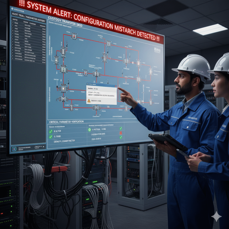
1.3 Verifying Critical Parameters of Smart Instruments
Modern transmitters, sensors, and flow computers store key configuration parameters in their internal menus.
Even small, unauthorized parameter changes can cause significant flow deviations—sometimes several percent or more.
This is especially critical in fiscal custody transfer applications.
Common preventive methods include:
a. Password protection
Used widely but can be bypassed in non-strict systems.
b. Data logging / parameter change history
Instruments with “data recall” or “audit trail” features automatically record all configuration changes that cannot be deleted.
This is highly effective for traceability.
c. Cross-verification through SCADA
Critical parameters are uploaded to the SCADA system and continuously compared with baseline values stored in the host computer.
Mismatch triggers alarms.
Among the three, audit trail + SCADA verification provides the strongest protection in modern plants.
1.4 Periodic Zero-Point Check of Differential Pressure Transmitters
Differential-pressure (DP) transmitters are widely used in:
Orifice plates
Venturi meters
Annubars / pitot tubes
Multi-range DP flowmeters
Because DP-based flow measurement follows a square-root extraction, even a slight zero drift has amplified impact on flow readings.
Example:
A 0.1% zero shift → approx. 3.16% flow error
Older standards such as HGJ1079-79 recommend monthly zero checks.
Although modern DP transmitters provide better long-term stability, zero drift still occurs due to:
Ambient temperature variations
Static pressure effects
Aging or installation stress
Periodic zero-point verification remains essential for reliable flow measurement.
2. Using Raw and Intermediate Data for Diagnostic Analysis
Modern smart instruments offer high transparency throughout the measurement process — from raw signals to intermediate computations to final outputs.
This greatly simplifies troubleshooting and increases user confidence.
Below is a practical example from the FC6000 Flow Computer system.
Case Study: Incorrect Pressure Type Setting
A Yokogawa DY vortex flowmeter was paired with an FC6000 flow computer to measure nitrogen flow.
During commissioning, the process engineer reported that the flow reading was 20% lower than expected.
Key observations:
Frequency signal input was correct
K-factor (flow coefficient) was correct
Pressure gauge indicated 0.4 MPa
Temperature was ambient
Upon reviewing the “Intermediate Calculation” screen, the temperature-pressure compensation factor was abnormally low.
Further checks revealed:
👉 The pressure type was mistakenly configured as absolute pressure instead of gauge pressure.
Once corrected, the flow reading immediately increased by approximately 25%, resolving the issue.
This example highlights the importance of:
Reviewing intermediate calculation nodes
Comparing raw and final values
Carefully verifying all compensation settings

3. Using Trend Analysis to Detect Potential Instrument Problems
Trend curves are valuable tools for uncovering subtle instrument issues that may not be visible in instantaneous readings.
3.1 Multi-Range Differential Pressure Flowmeters
In dual-range or triple-range DP flowmeters, the transition between ranges should be smooth and continuous.
Ideally, the low-range and high-range transmitters should agree closely at the switching point.
Normal system → smooth trend line, no visible step
Abnormal system → noticeable step or jump at switching point
Case Example
In a steam flow measurement setup, a three-range DP flowmeter underwent switching tests (“low → medium → high” and reverse).
The trend curve showed perfectly smooth transitions — indicating excellent transmitter matching and proper range switching logic.
If the system were improperly configured, trend curves would show:
Step changes at switching points
Abrupt discontinuities
Hysteresis or oscillations
Such signs indicate calibration errors, mismatched transmitters, or incorrect scaling.

Conclusion
Preventive maintenance for flow measurement systems requires a combination of:
Structured maintenance procedures
Transparent data analysis using raw and intermediate signals
Detailed trend monitoring to detect subtle abnormalities
Industry experience accumulated over years of operation
Modern smart instruments provide powerful diagnostic capabilities, but expert interpretation remains essential.
By leveraging self-diagnostic features, parameter audit trails, intermediate data, and trend analysis, maintenance engineers can identify early warning signs, reduce system downtime, and ensure reliable long-term operation.