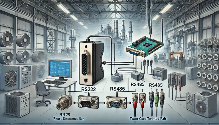
RS-485 is a robust and widely used communication standard, especially in industrial automation, where long-distance data transmission and multiple devices sharing a bus are common. However, despite its inherent noise immunity, improper wiring and external factors can lead to communication interference. In this article, we’ll delve into ways to manage interference in RS-485 systems and how to ensure proper hardware wiring for reliable communication.
Part 1: Handling RS-485 Communication Interference
Use Shielded Twisted Pair (STP) Cables Shielded twisted pair cables are essential in environments where electromagnetic interference (EMI) is present. The twisting of the signal wires helps to cancel out noise, while the shield adds an extra layer of protection from external interference. Here’s how to optimize the use of STP cables:
- Select Appropriate Cable: Use shielded cables designed for RS-485 communication. These cables typically have impedance of 100 to 120 ohms, which matches the requirements of RS-485 systems.
- Proper Shield Grounding: Connect the shield to ground at one point in the system to prevent ground loops. Grounding the shield at multiple points can introduce ground potential differences, leading to interference rather than reducing it.

2. Correct Grounding Grounding is one of the most crucial factors for ensuring stable RS-485 communication. Poor grounding can lead to increased susceptibility to interference, and voltage differences between grounds can introduce noise into the system. Here’s what to consider:
- Common Ground for All Devices: Ensure that all RS-485 devices share a common ground to minimize the ground potential differences between them. Ground potential differences can create noise that interferes with the signal transmission.
- Isolated Power Supply: In some cases, using an isolated power supply for different parts of the system can help reduce noise caused by ground loops.
3. Termination Resistors RS-485 is designed for long-distance communication, and when the cable is longer, signal reflections can occur at the cable ends, resulting in data errors. To mitigate this, use termination resistors:
- Place at Both Ends: A 120-ohm resistor should be placed between the A and B lines at both ends of the RS-485 bus. This resistor should match the characteristic impedance of the cable to minimize reflections.
- Avoid Over-Termination: Do not place termination resistors on every node, only at the physical ends of the bus, to avoid unnecessary power dissipation and signal degradation.

4. Limit the Number of Devices on the Bus While RS-485 supports up to 32 devices on a single bus, loading too many devices can weaken the signal. Here’s how to handle this:
- Use Repeaters if Needed: If more than 32 devices are needed or the bus length is long, consider using RS-485 repeaters to extend the network without overloading the bus.
- Ensure Proper Addressing: Each device on the RS-485 bus must have a unique address to avoid communication conflicts.
5. Implement Isolation Techniques Electrical isolation can provide protection against high-voltage transients and reduce noise. Isolation can be achieved using optocouplers or transformers. Here’s why and how to implement isolation:
- Optical Isolation: By adding optocouplers, you can electrically isolate the communication lines between devices, reducing the risk of noise from high-power devices or external electrical systems.
- Power Supply Isolation: Isolating the power supply can also prevent noise from coupling into the signal lines.
6. Use of Filtering Electrical noise from the environment can disrupt RS-485 communication. Filters can help reduce this noise:
- Power Line Filtering: Adding low-pass filters to the power supply lines can help block high-frequency noise from reaching the communication lines.
- Capacitive Filtering on Signal Lines: Small capacitors (in the range of 10pF to 100pF) can be placed between signal lines and ground to filter out high-frequency noise. Be careful not to use capacitors that are too large, as they could distort the signal.

Part 2: Proper Hardware Wiring for RS-485 Systems
Use High-Quality Twisted-Pair Cables RS-485 systems benefit from the use of high-quality twisted-pair cables. Here’s how to select and implement them:
- Cable Selection: Choose cables with a twisted-pair design to ensure that noise is effectively canceled out. The impedance of the cable should match the RS-485 standard (100 to 120 ohms). For distances up to 1200 meters, choose cables of 22 to 24 AWG.
- Twist Integrity: When installing, avoid untwisting the cables excessively at connection points, as this can reduce the effectiveness of the noise cancellation.
2. Maintain Adequate Distance from High-Voltage Lines Signal wires should be routed away from high-voltage power lines or equipment that could introduce noise into the system:
- Maintain a Safe Distance: Keep at least 12 inches (30 cm) of separation between RS-485 signal cables and high-voltage lines.
- Use Conduits: When RS-485 wiring must cross power lines, do so at right angles and consider placing the signal wires inside grounded metal conduits to shield them from EMI.
3. Consistent Grounding and Bonding Proper grounding and bonding ensure the overall system stability and noise immunity:
- Single-Point Grounding: Ensure that the RS-485 cable shield and the devices on the bus are grounded at a single point to prevent the formation of ground loops.
- Equipotential Grounding: If the RS-485 system spans long distances, use equipotential grounding systems to ensure that all devices share the same ground reference.

4. Signal Line Symmetry and Balanced Lines RS-485 is a differential signaling system, meaning the integrity of the signal depends on the symmetry of the A and B lines:
- Equal Length Wires: Ensure that both signal wires (A and B) are the same length and run parallel to each other, which ensures balanced transmission and reduces the likelihood of EMI.
- Avoid Sharp Bends: Do not introduce sharp bends in the cables, as this could affect impedance and signal quality.
5. Limit Cable Length and Avoid Excessive Daisy-Chaining While RS-485 can transmit data over long distances, overly long cables can introduce noise or degrade signal quality:
- Minimize Cable Length: Try to keep the cable length as short as possible, especially in noisy environments. While the RS-485 standard supports up to 1200 meters, shorter distances improve reliability.
- Avoid Daisy-Chaining Too Many Devices: Instead of daisy-chaining a large number of devices on a single bus, use star or tree topologies with repeaters where necessary.
6. Use Grounded Metal Conduits for Extra Protection In especially noisy environments, placing RS-485 cables inside grounded metal conduits provides additional shielding from interference:
- Proper Grounding: Ensure that the metal conduit is grounded properly at one point to prevent ground loop issues. Metal conduits can serve as an extra layer of protection against EMI.

Conclusion
RS-485 communication systems are highly reliable and robust, but their performance can degrade significantly due to interference if not properly handled. By following the guidelines outlined here—such as using shielded cables, proper grounding, isolation techniques, and correct wiring practices—you can minimize the impact of noise and interference, ensuring stable and efficient data transmission.
Implementing these practices not only protects the integrity of the data being transmitted but also extends the life and reliability of the communication system in industrial and commercial environments.
