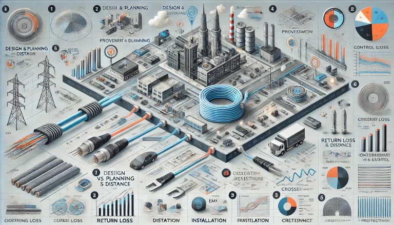
In some industrial environments, cable-related faults account for up to 50% of all system failures. Issues such as overloads, short circuits, and signal integrity loss frequently originate from poor-quality or improperly maintained cabling. For end users pursuing high-reliability automation, ensuring cable system integrity is mission-critical.
1. When and How to Evaluate Cable Quality
A robust cable quality assessment program should cover the entire product lifecycle, including:
📌 1.1 Timely Testing at Key Stages
To maintain system reliability, periodic testing of cabling systems should be implemented at the following checkpoints:
Design & Planning Stage
Product Selection & Procurement
Incoming Material Inspection
In-Process Testing
Final Commissioning & Acceptance
Operation & Maintenance
🛠️ Recommended Tools: Network cable testers, time-domain reflectometers (TDR), and OTDR analyzers for fiber.
📌 1.2 Redundancy and Backup Cables
For critical Ethernet and control signal cables, implementing redundant routing (e.g., ring topology or spare links) ensures minimal downtime. Faulty cables or segments can then be quickly bypassed or replaced.

2. Key Factors Affecting Cable Quality
Cable quality is influenced by a range of physical, electrical, and environmental parameters. The following indicators are essential for quality evaluation:
🔹 2.1 Insertion Loss (Signal Attenuation)
Refers to signal strength reduction over distance. Excessive loss leads to degraded communication performance.
Typical Range: < 2 dB/100m for Cat6 Ethernet cables.
🔹 2.2 Crosstalk (NEXT/ FEXT)
Unwanted signal coupling between adjacent wires causes communication errors.
Near-End Crosstalk (NEXT)
Far-End Crosstalk (FEXT)
Modern testing requires compliance with standards like TIA-568 and ISO/IEC 11801.
🔹 2.3 Return Loss
Measures signal reflections due to impedance mismatches. High return loss reduces system efficiency and increases bit error rates.
🔹 2.4 Shielding Integrity & EMC Resistance
In industrial environments, electromagnetic interference (EMI) from motors, drives, and power cables can severely affect signal integrity. Cables must feature:
Proper Braiding or Foil Shielding
360° Grounding at Termination Points
Use of EMC-compliant Cable Glands
🔹 2.5 Thermal, Mechanical, and Chemical Resistance
Cables in harsh environments should also meet requirements for:
Temperature Range (e.g., -40 to +105°C)
Abrasion Resistance
Oil, Chemical, or UV Exposure Protection
📦 Reference Standard Examples: UL 758, IEC 60228, GB/T 19666

3. Common Causes of Cable Failure
| Cause | Description |
|---|---|
| Overloading | Exceeding current capacity causes overheating and insulation damage |
| Improper Bending Radius | Sharp bends lead to conductor breakage or signal degradation |
| EMI Interference | Poor shielding allows electromagnetic noise infiltration |
| Connector or Termination Faults | Loose or corroded connectors increase resistance and data loss |
| Aging and Environmental Stress | Degradation due to temperature cycles, moisture, and UV exposure |
4. Recommendations for End Users and Integrators
✅ Set Quality Standards: Align procurement and installation with international norms (e.g., ISO/IEC 11801, UL standards)
✅ Invest in Testing Tools: Use handheld testers, TDRs, and loopback devices to verify performance periodically
✅ Document Everything: Maintain cable schematics, test records, and failure logs
✅ Train Technicians: Ensure installers understand cable handling, routing, grounding, and EMC practices
