Electrodes are critical components of an electromagnetic flow meter. Their condition directly affects measurement accuracy and long-term performance. This guide provides systematic methods to assess electrode health and identify common issues during field operation.
Part I: Methods for Evaluating Electrode Condition
1. Visual Inspection
Check the sensor body for physical damage.
Ensure sealing is intact and the display panel functions normally.
Examine the electrode surface for signs of contamination, corrosion, or scaling.
2. Contact Resistance Measurement
Use a digital multimeter to measure the contact resistance between the electrode and the liquid.
Normal resistance should be between 1 kΩ and 1 MΩ.
The resistance between terminals “1” and “2” and between “1” and “3” should be approximately symmetrical.
3. Check Internal Connectivity
Inspect the connection between electrodes and signal cables.
Ensure terminal screws are tightened and contact is reliable.
Rewire or replace cables if looseness or corrosion is detected.
4. Excitation Coil Resistance Test
Measure the resistance of the excitation coil to check for short circuits.
Normal resistance range: 30–170 Ω.
5. Insulation Resistance to Ground
Use a megohmmeter to test the insulation resistance between the excitation coil and ground.
The value should be greater than 20 MΩ; low values may indicate moisture ingress or insulation breakdown.
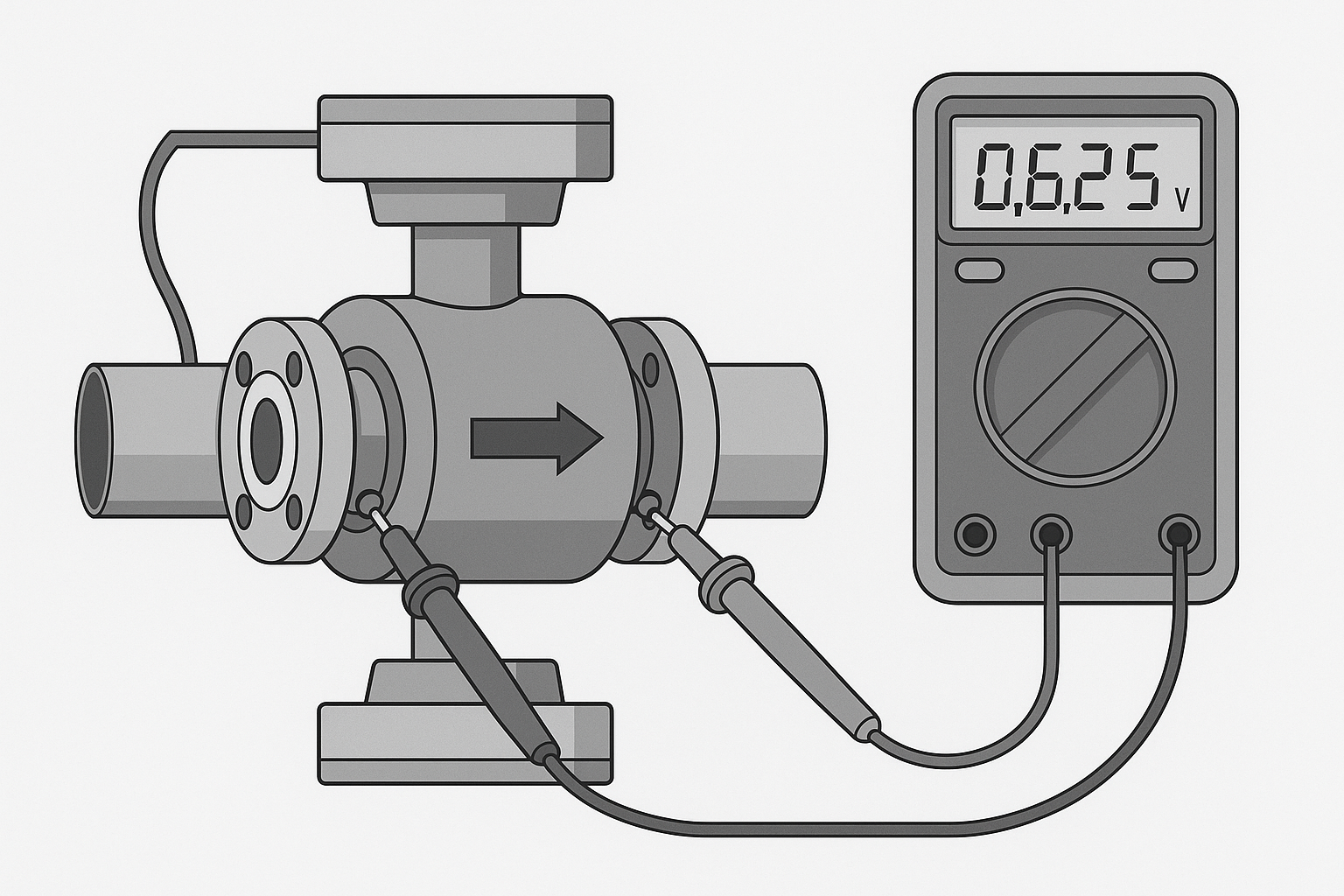
6. Electrode Potential Test
Use a multimeter or a dedicated electrode tester to measure electrode potential.
Abnormal readings may indicate electrode failure.
7. Electrode Terminal Inspection
Check whether the electrode terminal or connector is loose or oxidized.
8. Signal Stability Observation
Monitor the signal on the display. If the readings are unstable or fluctuate significantly, inspect the electrodes and signal cables.
9. Routine Cleaning and Maintenance
Periodically clean the electrodes, especially in conductive or scaling-prone media.
Ensure there is no buildup or blockage on the electrode surface.
Part II: Common Electromagnetic Flow Meter Issues and Troubleshooting
1. Zero Drift
Occurs when:
The pipe is not fully filled with liquid.
The liquid is moving during calibration.
Solution: Ensure the pipe is completely filled and the fluid is static before performing zero calibration. This can be achieved by closing the upstream valve after filling the pipe.
2. Full-Scale Display (Reading Max Value)
Possible causes:
Actual flow exceeds range.
Signal circuit is open.
Signal cable failure.
Incorrect wiring.
Sensor and transmitter mismatch.
Configuration errors in the device.
3. Reading Fluctuation or Noise
External interference sources:
Stray currents.
Static electricity.
Electromagnetic waves.
Magnetic field disturbances.
Internal causes:
Oxidized terminal contacts.
Poor contact on circuit board.
Contaminated electrodes.
Improper gasket installation.
Incomplete pipe filling or presence of air bubbles.
Inadequate grounding.
4. Reading Too High or Too Low
Possible causes:
Improper zero-point calibration.
Improper sensor installation (e.g., not in a vertical pipe or wrong position).
Insufficient straight pipe length upstream and downstream.
Air bubbles or partial pipe filling.
Degraded insulation on the electrode.
By following these diagnostic methods, you can accurately determine whether the electrodes or other components of the electromagnetic flow meter are malfunctioning, ensuring timely maintenance and reliable system performance.