In process control systems, buffer tank level control (LIC) is typically considered a “slow-variable” control loop. Usually, a level controller stabilizes the level by cascade controlling the feed flow rate (FIC1). However, when a second feed flow rate controller (FIC2) is added to the system, new challenges arise:
How should control authority be distributed between two manipulated variables?
How can we maintain the compatibility of the existing system while leveraging the optimization potential of FIC2?
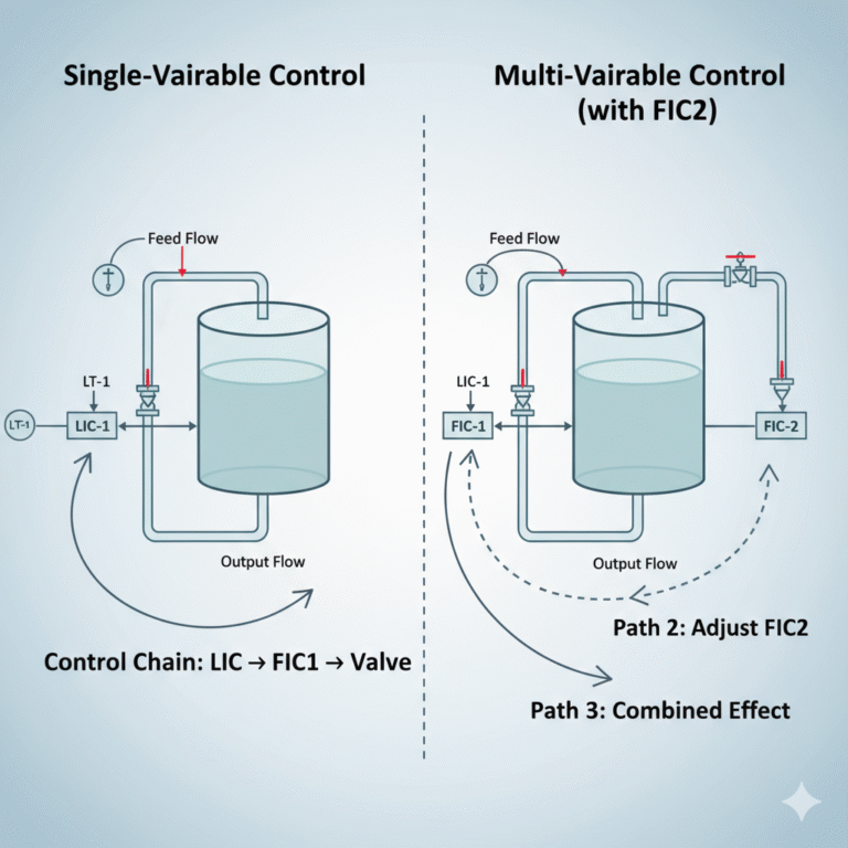
From Single-Variable to Multi-Variable Control
In the original system, the control chain is clear: Level (LIC) → Flow rate (FIC1) → Valve. With the addition of FIC2, two potential control paths emerge:
Adjusting the feed rate through FIC1.
Adjusting the auxiliary flow rate through FIC2.
Or a combined effect from both.
While more control options may seem advantageous, improper handling can lead to control conflicts, system oscillations, and increased level fluctuations. Thus, coordinating the roles of multiple manipulated variables becomes the key to control system design.
Three Fundamental Principles for Control Design
To achieve a stable, maintainable, and scalable system, three principles must be adhered to in the design:
One Manipulated Variable per Controlled Variable: Each controlled variable should have one primary manipulated variable, avoiding multi-headed control.
Prefer Simple Loops: Simple structures are superior to complex nested loops, as they reduce debugging difficulty and system uncertainty.
Compatibility with the Existing System: New control logic must smoothly integrate with the existing DCS (Distributed Control System), avoiding a complete overhaul.
These seemingly simple principles are the foundation of most successful control systems.
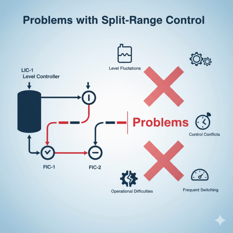
Problems with Split-Range Control
When dealing with dual flow control, many engineers consider split-range control, where FIC1 and FIC2 are separately adjusted. However, this approach often creates more problems than it solves, such as:
Split-range control is better suited for direct valve control, not indirect control via auxiliary loops (FIC).
Differences in response speed, dead zones, and linearity between FIC1 and FIC2 can lead to competitive control.
Setting the switching points for split-range control is complex and often incompatible with existing LIC cascade control.
Therefore, this solution often leads to frequent switching, level fluctuations, operational difficulties, and other issues.
The Proper Role of FIC2
Instead of having FIC2 “compete” for control, it can be optimized as an execution enhancement tool. Without changing the main level control logic, FIC2 can take on the following roles:
Maximizing Flow Rate: Increase the feed rate as much as possible within the level setpoint range, optimizing production capacity and feed efficiency.
Optimizing Target Flow Rate: Automatically adjust based on production plans or energy consumption models, enabling energy savings and cost reduction.
Proportional Coordinated Control: FIC2 adjusts proportionally based on FIC1 changes, balancing multiple feed lines.
Action Suppression Control: Implement dead zones and delays to avoid frequent adjustments, improving system longevity and stability.
The core idea behind this design is to make FIC2 a “flexible optimizer” rather than a second control center.
PID-Level Implementation Methods
By skillfully using PID structures and signal logic, FIC2 can easily implement the following functions in a DCS system:
Proportional Follow Control: Set the FIC2 setpoint to be a proportional coefficient of FIC1’s output.
Offset Optimization Control: Set the FIC2 setpoint as a reference value plus compensation for deviation.
Limit and Constraint Control: Set upper and lower limits for FIC2 to prevent excessive adjustments.
Dead Zone/Delay Control: Reduce high-frequency adjustments to stabilize the system.
These methods are highly compatible and do not require changes to the primary control loop, ensuring high feasibility in engineering applications.
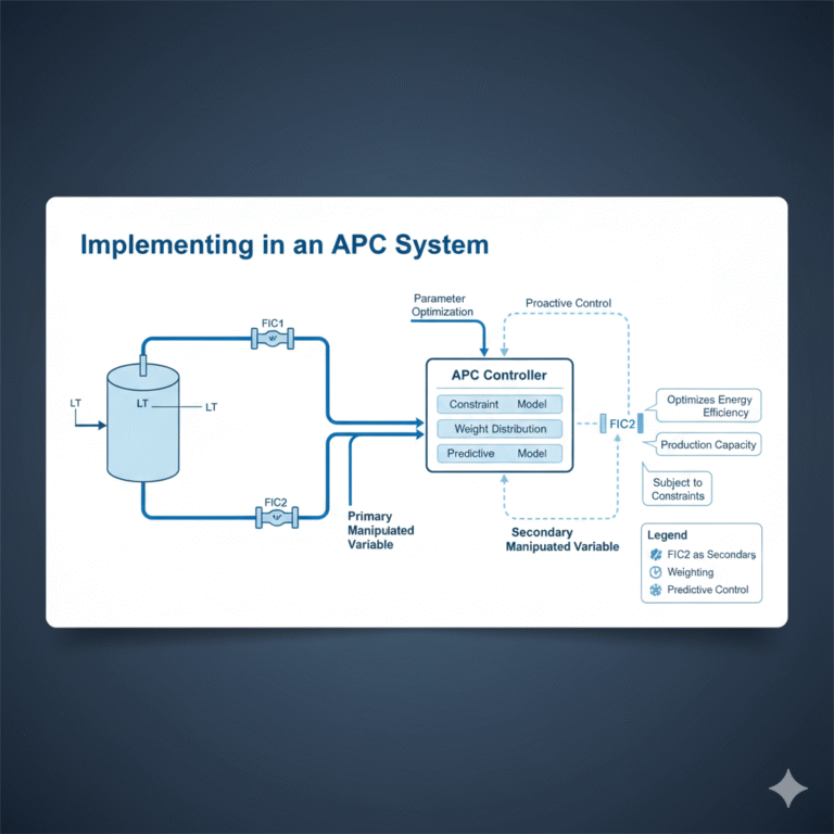
Implementing in an APC System
For systems with an existing Advanced Process Control (APC) system, intelligent control can be achieved through modeling and parameter optimization. Methods include:
Setting FIC2 as a “secondary manipulated variable.”
Using APC constraint models to define the operational boundaries for FIC2.
Adjusting the weight distribution between level, energy consumption, and flow rate to find the optimal balance.
Integrating predictive models that enable the system to respond to level fluctuations proactively, achieving active control.
In this way, APC can optimize level stability, energy efficiency, and production capacity without interfering with the original control logic.
Key Considerations in Engineering Implementation
Dynamic Response Matching: Ensure the time constants of FIC1 and FIC2 are close to avoid “fighting” with each other.
Signal Delay Control: If FIC2’s signal comes from a remote location, consider compensating for communication delays.
Clear Interfaces: The operator interface should clearly differentiate between primary control and auxiliary control logic.
Startup Strategy: FIC2 should be enabled gradually—first for observation, then optimization, and finally closed-loop control.
This “progressive control optimization” approach aligns well with on-site maintainability principles.
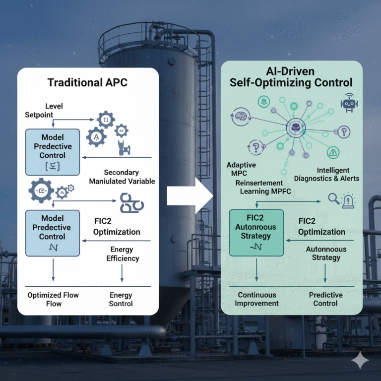
From APC to AI-Driven Self-Optimizing Control
As industrial intelligence advances, AI-integrated APC systems, or “self-learning control systems,” are emerging. These technologies include:
Adaptive MPC: Real-time model adjustments that automatically optimize the FIC2 strategy based on operating conditions.
Reinforcement Learning Control: The system autonomously identifies the optimal flow distribution based on experience feedback.
Intelligent Diagnostics and Alerts: AI identifies performance degradation and automatically adjusts parameters.
These technologies are transforming the challenge of managing “one level, two flow rates” from an engineering dilemma into an experimental platform for intelligent optimization.
Conclusion
The ultimate goal of a control system is not to make the structure more complex, but to make its operation more coordinated, efficient, and stable. After adding FIC2, the key is to position it as an auxiliary optimizer rather than a competitor for control authority.
“Simple and optimal” means pairing systems first, then optimizing; stabilizing first, then adding intelligence. When control loops are simple and elegant, the system will naturally achieve “less adjustment, more stability, and higher output.”