In the field of instrumentation, theoretical knowledge is like the wrench in your hand—often overlooked but essential when it’s needed. Whether you’re preparing for certification exams or looking to strengthen your practical skills, understanding circuit diagrams, sensor principles, and troubleshooting logic is crucial. This series will continue to update, offering both theoretical foundations and practical exercises that can help you build solid skills, even during short spare moments. For those who want to avoid detours and quickly fill knowledge gaps, let’s solidify the theoretical base for more confident, effective work!
1. Measuring Current in Actuator Circuits
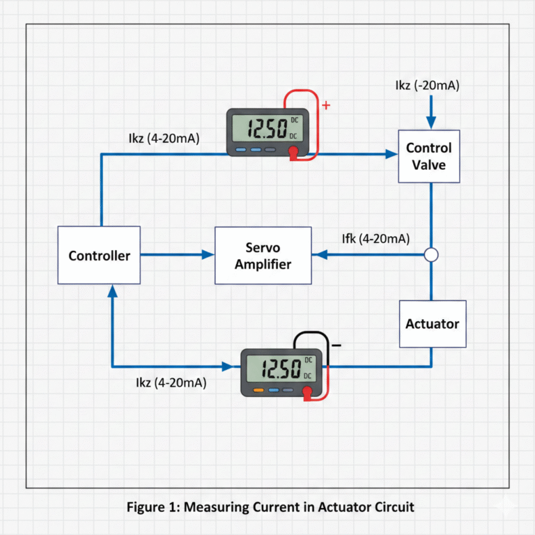
Figure 1 illustrates an actuator circuit. By using a multimeter in DC current mode, you can measure the current of control signals or valve position feedback signals, helping to determine whether the actuator is functioning correctly.
Figure 1: Measuring Current in Actuator Circuit
When the current of Ikz and Ifk is within the 4-20mA range, it indicates that both the controller and the actuator are working properly.
If the current of Ikz exceeds 20mA, there may be a short circuit in the load or an issue with the controller. In this case, check the servo amplifier and controller, and ensure the controller’s fault-holding function is disabled. Verify the status of the controller’s AO card.
If Ifk exceeds 20mA, first check if the control valve is fully open. If the valve is not fully open, the valve position feedback circuit may be faulty.
If Ikz shows no current (0mA), it may indicate a failure in the control loop, such as a malfunction in the AO card or an open circuit between the controller and the servo amplifier.
If the current of Ifk is ≤4mA, check whether the valve is fully closed. If the current is 0mA, this could indicate an issue with the feedback circuit, such as a power interruption or malfunction in the actuator’s feedback mechanism.
2. Indirect Methods for Measuring Current
Measuring current typically requires breaking the circuit and inserting an ammeter, which can be cumbersome. However, if the circuit includes a low-resistance, non-inductive resistor, you can use a multimeter in DC voltage mode to measure the voltage across the resistor. Using Ohm’s law, you can calculate the current flowing through the resistor. Another approach is to temporarily add a current-limiting resistor to the circuit to measure the current indirectly.

3. Precautions When Measuring Current
Before measuring current, always cut off the power to the device being tested. After properly connecting the multimeter, power on the circuit to take the measurement—do not insert the multimeter when the system is powered. Never connect the multimeter leads across the power supply directly, as this may damage the multimeter.
Since both the power supply resistance and load resistance are small, always select a higher current range initially to reduce the shunt resistance and minimize voltage drop across it. This will improve measurement accuracy.
When measuring current, the multimeter should be connected in series with the circuit, ensuring that the same current flows through both the multimeter and the circuit. If you are unsure of the current size, begin with the highest current range and gradually reduce it to an appropriate level.