The flow signal of the electromagnetic flowmeter is based on the measured conductive liquid as the reference potential. The conductive liquid in the entire measurement pipe is regarded as a conductor with zero resistance. The two electrodes form a differential signal voltage to the conductive liquid. Therefore, if the signal contact point is unreliable, the reference will be unstable and the measurement will be unstable.

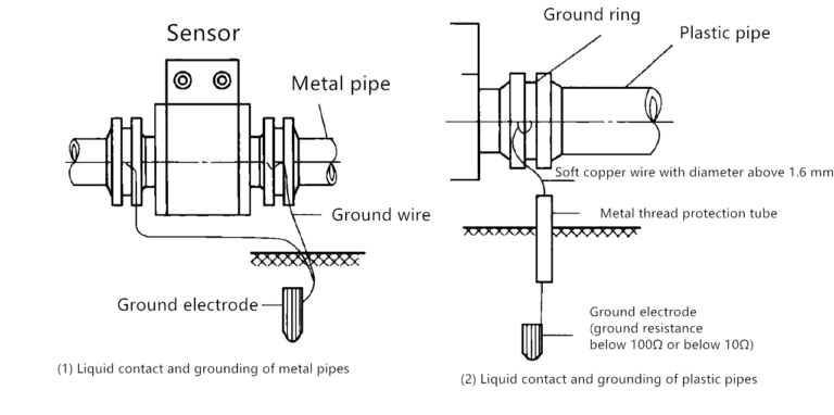
Metal pipes are often connected to the earth. Sometimes ground currents from industrial power grids, such as three-phase unbalanced currents, flow through pipelines. If the pipeline and the flowmeter are not connected, ground current and three-phase unbalanced current may produce a large voltage drop on the flowmeter, causing interference to the flow signal. Therefore, it is hoped that the metal pipes before and after the flow meter and the flow meter will be connected together with metal wires and connected to the earth.
Large diameter pipes can be very long, resulting in test lines that are not long enough to completely cover the entire pipe. Secondly, the resistance of the conductive liquid at the reference potential cannot be ignored and cannot simply be regarded as zero. In addition, there may be severe corrosion on the inner wall of large-diameter metal pipes, which will affect the conduction of current. Therefore, relying on the metal pipe itself to contact the liquid to ensure the conduction of electric current is unreliable.
To address these issues, recommendations have been made to ground metal pipes. Grounding metal pipes can effectively stabilize the reference and provide a reliable current conduction path while reducing test inaccuracies caused by factors such as insufficient pipe length and inner wall corrosion. It acts as a stable reference through grounding.

Test line
“Test line” generally refers to a line of electrodes used to test or monitor the electrical potential within a pipeline. In pipeline corrosion monitoring and anti-corrosion control, it is often necessary to measure the potential within the pipeline to evaluate the corrosion situation and take corresponding protective measures.
A test pipeline is a circuit system used to arrange electrodes inside the pipeline and connect it to test instruments to measure the potential on or around the pipeline surface. Such measurements can help engineers understand how corroded a pipe is and whether further maintenance or repair measures are needed.

For split type flowmeters, the excitation wire generally uses PVC sheathed double-core multi-strand round copper wire; the signal line generally uses PVC sheathed metal mesh shielded double-core multi-strand round copper wire, and the metal shielding mesh is usually used as a grounding, Wetted line.
If you use a two-core multi-shielded cable, please note that the metal shielding net outside each core wire is open-circuited at the sensor terminal and must not be connected to the flowmeter casing or the earth.
The metal shielding net outside the core wire should be connected to the signal excitation shielding end of the converter terminal block.
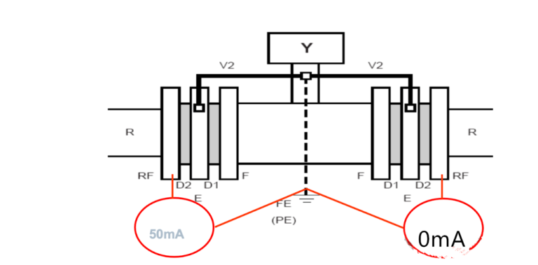
The figure below illustrates an example of interference from pipes

Isolate each bolt and nut
