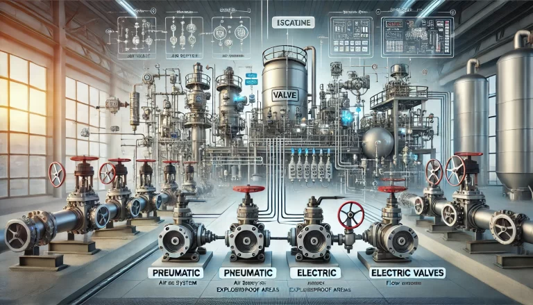
In industrial pipeline systems—especially within chemical plants—selecting the right type of valve is critical to ensuring process safety, efficiency, and maintainability. Among the most commonly used are gate valves and globe valves, each with distinct structural features, sealing mechanisms, and application scenarios. This article provides an in-depth comparison to assist engineers, procurement professionals, and operators in making informed decisions.

1. Gate Valve: Structure, Function, and Features
Gate valves operate by raising or lowering a wedge-shaped or parallel gate to start or stop flow. The motion is linear and typically along the axis of the pipeline.
1.1 Sealing Mechanism
Self-sealing: Uses fluid pressure to press the gate against the seat. Less common.
Force-sealing: Most common type, requiring external force (manual, electric, pneumatic) to press the gate against the seat for tight sealing.
1.2 Types of Gate Valves
Based on sealing surface:
Wedge-type gate valve: Single wedge, double wedge, or elastic wedge.
Parallel gate valve: Single or double disc.
Based on stem design:
Rising stem (outside screw and yoke)
Non-rising stem (concealed thread)
1.3 Working Principle
When opening: turning the handwheel raises the stem and lifts the gate from the seat, allowing unobstructed flow. When closing: the gate descends to tightly seal the flow path.
1.4 Key Advantages
Low flow resistance: Minimal obstruction in full open state.
Bidirectional sealing: Fluid can flow from either direction.
Simple internal flow path: Easier for high-flow applications.
Reduced water hammer: Slower closing action helps minimize pressure surges.
Cost-effective structure: Short length and simple fabrication.
1.5 Limitations
Large installation space: High profile due to long stem travel.
Long operation time: Opening/closing requires multiple turns.
Maintenance complexity: Harder to repair internal sealing surfaces.

2. Globe Valve: Structure, Function, and Features
Globe valves feature a disc (plug or cone-shaped) that moves perpendicular to the seat to control flow.
2.1 Sealing Mechanism
Globe valves are force-sealing devices: they require applied pressure to achieve proper sealing.
2.2 Flow Characteristics
Typically unidirectional.
Higher resistance due to change in flow direction.
Capable of fine flow control (not suitable for high-viscosity or slurry media).
2.3 Key Advantages
Reliable sealing: High pressure applied on small sealing area ensures tight closure.
Longer service life: Minimal sliding between disc and seat reduces wear.
Double sealing options: Bellows seal + gland packing for enhanced leak prevention.
Safer for hazardous media: Zero-leakage designs available.
2.4 Limitations
Higher flow resistance: Due to S-shaped internal flow path.
Greater actuation force needed: Must overcome system pressure when closing.
Not ideal for rapid opening/closing: Higher torque required.

3. Application Scenarios Comparison
| Feature / Requirement | Gate Valve | Globe Valve |
|---|---|---|
| Main Function | Flow shut-off | Flow regulation and shut-off |
| Flow Resistance | Low | Moderate to high |
| Flow Direction | Bidirectional | Mostly unidirectional |
| Sealing Reliability | Moderate | High (especially with bellows seal) |
| Installation Space | Large | Compact |
| Opening/Closing Speed | Slow | Moderate |
| Typical Applications | Water lines, power plants, large pipes | Chemical dosing, pressure control loops |

4. Summary
In chemical plants:
Use gate valves where tight shut-off and low resistance are priorities, especially in large-diameter lines and water/steam pipelines.
Use globe valves in scenarios requiring precise flow control, high sealing reliability, and safety in handling toxic or high-pressure fluids.
Both valve types are indispensable. Selection should depend on media characteristics, system pressure, installation constraints, and control needs.
If you need help specifying the right valve for your system, contact our engineering support team.
