1. Background: Persistent Diaphragm Failures in DCS Level Transmitters
In a 450,000 tons/year polypropylene (PP) production plant using LyondellBasell’s gas-phase process, frequent failures occurred in level transmitters installed on Reactor #3 during the production of impact-resistant polypropylene. These failures were specific to the DCS-linked level transmitters, which required diaphragm replacement nearly every month, while a similar SIS-linked level transmitter—just 1.75 meters higher—remained fully operational under the same process conditions.
This issue raised critical questions:
Why do only the DCS transmitters fail?
Is it due to poor design, the nature of the impact-resistant PP, or both?
Why did even wear-resistant diaphragms (e.g., coated versions) still fail prematurely?
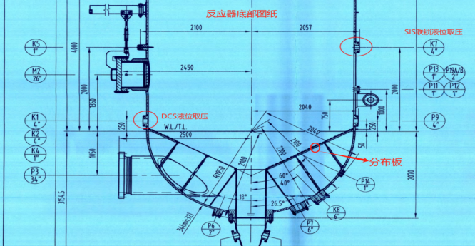
2. Process Description and Instrument Configuration
The reactor was equipped with three differential pressure (DP) level transmitters:
Two connected to the DCS, with tapping points at positions K1 and K2.
One connected to the SIS (Safety Instrumented System), tapping from position K7.
All transmitters had:
High-pressure side: flange-mounted diaphragm seals inserted into the reactor wall.
Low-pressure side: impulse tubing with purging air.
The difference in tapping positions:
DCS transmitters: located lower, directly on the conical distributor plate.
SIS transmitter: located 1.75 meters higher, away from the turbulent zone.
3. Root Cause Analysis
Inspection of failed transmitters revealed ruptured diaphragms, including those using hardened alloys like 316L and wear-resistant coatings. The cause was traced to:
External mechanical damage, not transmitter quality.
The conical distributor plate introduced cyclonic flow of polymer powder.
Impact-resistant PP pellets, being denser and more abrasive, were repeatedly striking the flush-mounted diaphragm, leading to fatigue and rupture.
In contrast, the SIS tapping point—positioned higher above the turbulent zone—avoided such damage.
Summary of failure characteristics:
| Feature | DCS Transmitters | SIS Transmitter |
|---|---|---|
| Tapping position | K1/K2 (lower) | K7 (1.75m higher) |
| Installation | Flush diaphragm | Flush diaphragm |
| Failure occurrence | Monthly | None |
| Material | 316L / coated diaphragm | 316L |
| Cause | Direct impact from rotating polymer | Minimal particle contact |
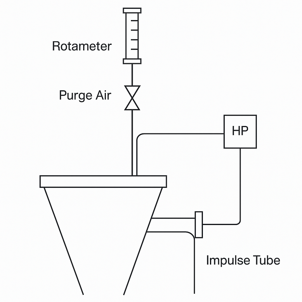
4. Modification Strategy: Transition to Remote Impulse Tube Tapping
To address the issue, the engineering team decided to abandon flush-type diaphragm tapping for the DCS transmitters and implement a remote impulse pipe + purge air solution.
Key changes included:
Structure Retention:
The original diaphragm seal structure was retained to ensure compatibility with the existing nozzle.
This minimized dead zones and avoided deposition or polymerization of reactive materials.
Impulse Tube Integration:
A 12 mm diameter impulse tube was inserted into the reactor through the original diaphragm center hole.
The impulse tube extended 20 cm into the reactor and was bent in the same direction as the internal flow to minimize impact from solid particles.
Purge Air Enhancement:
A rotameter-based purging system with:
One-way valve
Flow control
Added continuous low-flow purge during operation and automatic high-flow purge via bypass logic when needed.
Logic sequence optimized for:
No-disturbance switchover: Measurement data retained pre- and post-blowback.
Condition-based purging: Triggered based on reactor load or pressure.
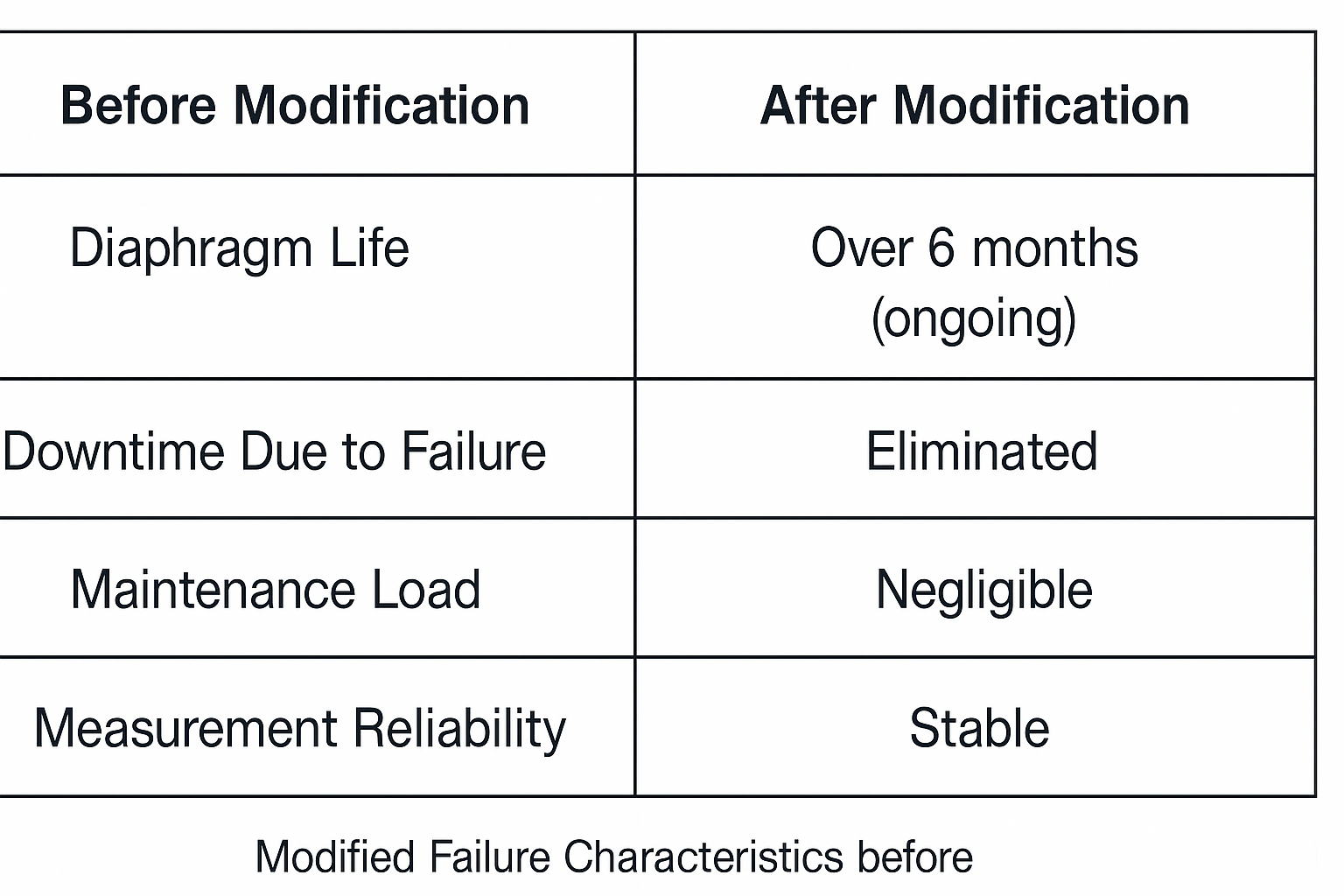
5. Post-Modification Results
After implementation:
Zero diaphragm failures observed over months of impact-resistant PP production.
Measurement remained accurate and stable.
No disruptions during purge cycles due to control logic optimization.
| Metric | Before Modification | After Modification |
|---|---|---|
| Diaphragm life | ~1 month | Over 6 months (ongoing) |
| Downtime due to failure | Frequent | Eliminated |
| Maintenance load | High | Negligible |
| Measurement reliability | Unstable | Stable |
6. Conclusion & Applicability
This case demonstrates how a seemingly minor mechanical redesign—relocating the tapping point and using impulse tubing with proper purge logic—can eliminate persistent instrument failures in harsh particulate environments.
Lessons learned:
Flush diaphragms, while compact, are vulnerable in abrasive or cyclonic flow zones.
Properly designed impulse tapping with purging ensures both longevity and measurement integrity.
The 1.75-meter difference in height, though small, created a significant variation in environmental stress.
This modification method is potentially applicable to other similar scenarios involving:
Aggressive polymerization zones,
Fluidized beds,
Cyclone separators,
Abrasive powder handling.