In the commissioning of large-scale boiler inlet water flow meters at a major power plant in Jiangsu, China, the flow measurement taken from one of the three pressure tapping points consistently showed higher readings compared to the other two. Despite thorough checks on the instruments and installations, the cause of this abnormality could not be identified. Given that the flow signal directly affects safety interlocks, this discrepancy was far from a trivial issue. Have you encountered a situation where “the instruments are fine, but the data seems off” during commissioning? This practical case study may help you understand the root cause of such issues.
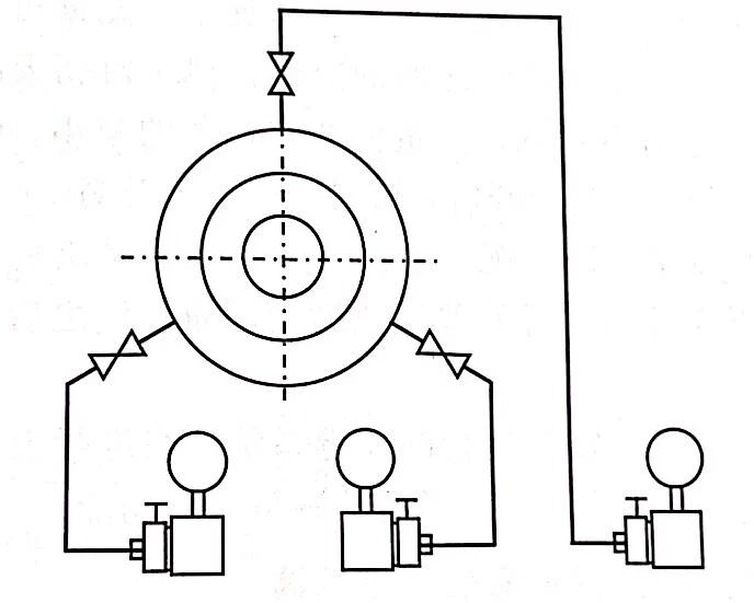
At the large power plant in Jiangsu, the boiler inlet water flow is crucial for safety interlocks, requiring high reliability. To achieve this, a standard orifice plate was installed on the horizontal inlet pipe, with three sets of differential pressure (DP) signal tapping points. These tapping points were evenly distributed around the circumference of the pipe, as shown in Figure 1. However, the tapping point facing upwards consistently recorded higher flow readings than the other two. The commissioning team repeatedly checked the instrument installation and calibrated the three differential pressure transmitters, but no issues were found.
Figure 1: Distribution of Pressure Tapping Points on the Horizontal Pipe
The issue was finally traced to the improper slope of the impulse tubing for the upward-facing tapping point.
When water flows through the orifice plate in the pipeline, microbubbles may form due to gas dissolved in the water. These gas bubbles escape at the orifice plate’s upstream side and enter the positive pressure tube of the upward-facing tapping point. Due to fluid statics, the differential pressure signal sent to the DP transmitter from this tapping point is slightly higher than that from the downstream tapping points. The downstream tapping points are not affected by the water flow impact and thus do not experience gas separation.
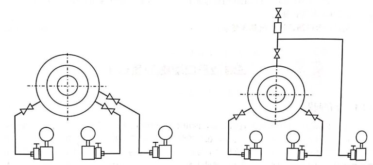
Solution 1: Relocate the Upward-Facing Tapping Point
One solution is to relocate the upward-facing tapping point below the horizontal line, ensuring proper slope for the impulse tubing, as shown in Figure 2. This adjustment will prevent gas separation and stabilize the differential pressure measurement.
Solution 2: Install a Gas Collector on the Positive Pressure End
Another solution is to install a gas collector at the highest point of the positive pressure side of the impulse tube, allowing periodic venting of any accumulated gas, as shown in Figure 3.
Verifying the Gas Accumulation in the Impulse Tube
The above explanation about gas accumulation in the positive pressure side of the impulse tubing is based on principle analysis. Since direct visual confirmation isn’t possible, indirect verification is needed. The simplest method is to purge the line: when the flow is stable, first record the instantaneous flow value from the upward-facing tapping point and the flow difference between it and the other two tapping points. After purging the line at the upward-facing tapping point, reopen the valve, and you will notice a significant decrease in the flow value. Normal flow readings will be restored, but over time, as gas accumulation resumes, the flow reading will gradually increase again.
Why does the flow decrease after purging the line? The elevated flow readings were caused by the accumulated gas in the positive pressure tube. Due to fluid statics, the DP transmitter recorded a higher differential pressure. After purging the line, the gas was removed, restoring normal measurements.
Safety Interlocks and Critical Operations
Before performing the purge operation, ensure that the safety interlock system is temporarily disabled and re-enable it once the checks and calibration are completed. The safety interlock system is essential for the safe operation of large-scale boilers and must be handled with care during troubleshooting.
Why Does Relocating the Tapping Point Solve the Flow Discrepancy?
The key to preventing gas accumulation lies in relocating the tapping point below the horizontal line. When the tapping point is positioned upwards, the gas bubbles in the water can rise into the vertical impulse tube due to the density difference between the gas and water. By relocating the tapping point below the horizontal line, the gas bubbles are prevented from entering the tube, ensuring accurate differential pressure readings. Additionally, any small gas bubbles in the impulse tube will rise into the main pipe, which helps maintain the integrity of the differential pressure signal.

Conclusion
This case study highlights a subtle yet critical detail that can lead to inaccurate flow measurements in boiler inlet water systems. By addressing the correct placement of tapping points and considering potential gas accumulation, the accuracy and reliability of flow measurements can be significantly improved. Proper calibration, installation, and periodic checks are essential in ensuring the safety and performance of such systems.