Accurate and reliable flow measurement requires periodic calibration. However, calibration intervals vary significantly depending on the instrument type, process medium, operating conditions, and industry compliance requirements. This document provides a comprehensive, instrument-specific overview of recommended calibration periods, key technical checkpoints, calibration methods, and adjustment rules widely adopted in water treatment, chemical, oil & gas, and industrial process applications.
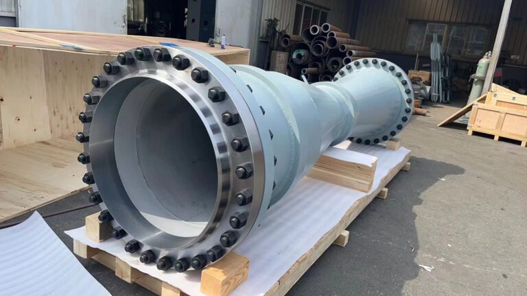
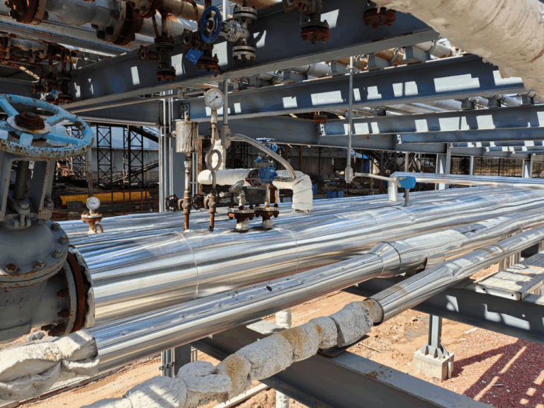
1. Differential Pressure Flow Meters
(Orifice plates, Venturi, V-cone flow meters)
Recommended Calibration Interval
Normal service (clean media, stable temperature/pressure): 12–24 months
Harsh service (corrosive/dirty media, high temperature/pressure): 6–12 months
Custody transfer / safety-critical loops: Every 6 months (mandatory in many jurisdictions)
Key Calibration Parameters
DP–flow linearity
Zero drift
Span accuracy
Orifice/V-cone wear (edge erosion ≥0.1 mm requires replacement)
Calibration Methods
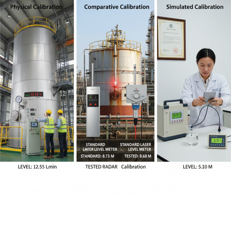
1) Field calibration
Parallel comparison with a certified DP device
Reference measurement using a portable ultrasonic flow meter
2) Laboratory calibration
Use a certified pressure calibrator (deadweight tester or piston gauge)
Temperature and pressure compensation modules must be validated
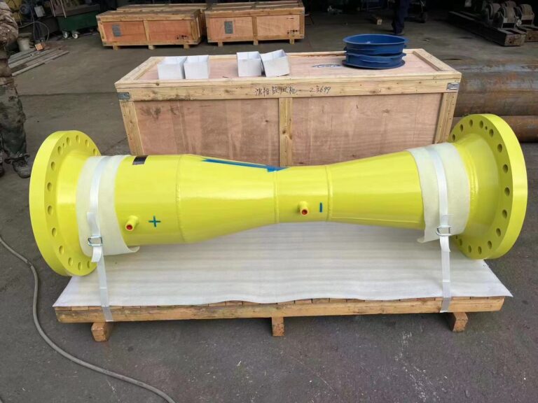
5. Vortex Flow Meters
Recommended Calibration Interval
Gases/steam: 18–24 months
Liquids (clean media): 12–18 months
High-temperature steam (>300°C): 12 months
Key Calibration Parameters
Frequency–flow linearity
Sensor sensitivity and signal conditioning
Zero drift and noise filtering
Calibration Methods
1) Field calibration
Use a certified reference vortex or electromagnetic meter
For steam: record pressure & temperature to recalculate standard flow
2) Laboratory calibration
Test vortex shedding frequency under controlled flow conditions
Replace damaged piezoelectric sensors before calibration
Important Notes
Clean the bluff body to remove scale deposits
Avoid damaging the sharp edges of the vortex generator
6. Calibration Interval Adjustment Rules
1. Condition-based adjustment
If a flow meter experiences two or more failures within one cycle, shorten the interval by 50%.
2. Process change adjustment
If the medium or operating conditions change significantly (e.g., clean water → sludge), shorten interval by 30–50%.
3. Industry regulations
Chemical plants Must comply with standards such as GB 50093-2013, limiting safety-loop instrument calibration to ≤12 months.
Oil & gas / natural gas custody transfer Follow JJG 1037-2008 and similar standards requiring calibration every 6 months.
Conclusion
Regular calibration is essential for ensuring stable, accurate, and compliant flow measurement in industrial applications. By following the recommended intervals and technical guidelines provided in this document, users can significantly reduce measurement uncertainty, extend instrument life, and comply with industry standards.
If you require calibration services, factory verification, or third-party traceable certificates, we are available to support your specific application.