This document outlines key inspection points during flow meter installation. Adhering to these guidelines ensures long-term reliability, accuracy, and safety of the instrumentation in industrial environments.
I. Mechanical Installation Checks
Temporary Gasket Installation
Temporary gaskets must be used during initial installation to prevent damage to flange sealing surfaces.
Flow Direction Verification
Ensure the flow arrow on the instrument aligns with the actual process flow.
Avoid placing flow meters near strong vibration sources.
Pre-Blowdown Removal
Flow meters must be removed during pipeline blowdown or purging operations.
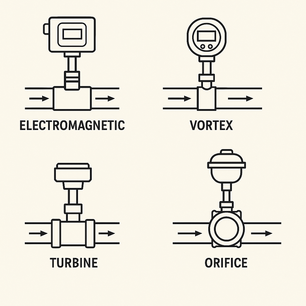
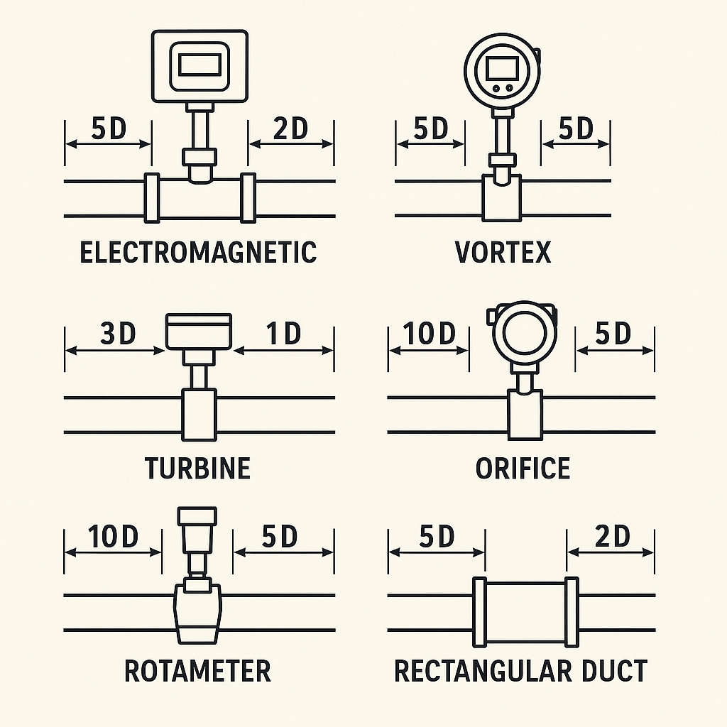
Straight Run Requirements
Flow Meter Type
Upstream (D)
Downstream (D)
Electromagnetic
≥5D
≥2D
Vortex
≥15D
≥5D
Turbine/Helical (Screw)
≥3D
≥1D
Orifice Plate
≥10D
≥5D
Rotameter
≥10D
≥5D
Rectangular Duct
≥5D
≥2D
Target Flow Meters
Ensure the target plate is installed perpendicular to the flow (aligned exactly vertical to pipe axis).
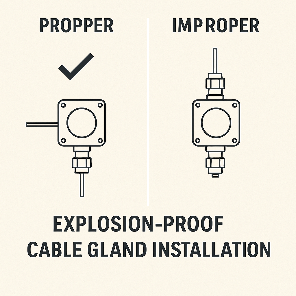
Explosion-Proof Cable Gland
Must be installed and secured. Orientation should avoid upward-facing cable entries to prevent moisture ingress.
Flange Bolt Protrusion
Bolts must protrude 5–10 mm beyond the nut after tightening.
Accessibility
Transmitter must be easily accessible for wiring; the display should be positioned for convenient reading.
II. Electrical Checks
Power Supply Wiring (4-wire Meters)
Confirm correct power polarity and voltage levels per wiring diagram.
General Wiring Standards
Check:
Cable terminals are correctly made.
Shielded layer is not exposed unnecessarily and properly grounded.
Ferrules are crimped securely.
Terminal screws are tight.
III. Special Considerations
Flange Welding
Flange and pipeline welding must not be done with sensors attached to avoid thermal or mechanical damage.
Cleanliness Before Installation
Ensure all inner surfaces of the sensor and pipeline are clean and free from debris or welding residue.
Protective Covers
Remove protective shells/caps from both ends of the meter before installation.
Electromagnetic Flow Meter Grounding
Grounding wires must be firmly connected to flange bolts. Proper grounding is essential for signal stability.
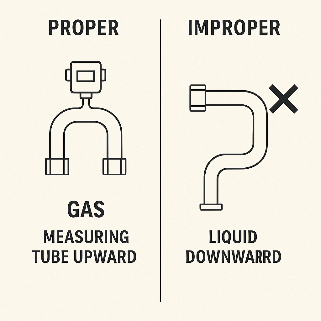
Coriolis Mass Flow Meter Orientation
For gas measurement, install with measuring tube upward.
For liquid measurement, install with measuring tube downward to avoid gas/liquid retention.
Grounding Rings (for Electromagnetic Type)
Ensure proper installation of grounding rings where specified to enhance signal stability and accuracy.
Maintenance Space
Confirm there is enough space around the installation point for future calibration and maintenance operations.