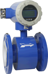
In the measurement and control of industrial production processes such as petrochemicals and fertilizers, a large number of electromagnetic flowmeters that can solve the problem of medium corrosion are used. However, in the production sites of these industries, there are often explosive gases and vapors from flammable liquids. Therefore, explosion-proof electromagnetic flowmeters are required.
Regarding explosion-proof, you should be clear about the principle, method, classification, and standard of explosion-proof, establish a preliminary understanding of explosion-proof, and understand the basic knowledge of explosion-proof. The explosion occurred when three conditions were met at the same time:
a. There are explosive substances on site, such as explosive gas;
b. There is oxygen on-site;
c. There are explosive sources on-site, such as electric sparks with enough energy or high enough surface temperature of objects.
Obviously, by eliminating any one of the three conditions, explosion protection can be achieved. Because oxygen is everywhere, it is difficult to control. Therefore, controlling explosive gases and detonating sources are the two most common explosion-proof principles, and the explosion-proof principle of controlling the scope of the explosion is often used in the instrument industry.

Artificially create a space free of explosive gas at the dangerous site, and install the instrument in it. The typical representative is the positive pressure type explosion-proof method Ex P0. The method is to install the instrument in a sealed box, filled with clean air or inert gas, and keep the air pressure inside the box slightly greater than the air pressure outside the box so that explosive gases cannot enter the box. An explosion-proof method is used to store positive pressure nitrogen in the sensor sealing shell, and the converter sealing shell is designed with clean air or inert gas inlet and exhaust joints. The explosion-proof method is the electromagnetic flowmeter with the principle of positive pressure explosion-proof.
The explosion is artificially confined to a limited range, and the explosion in this range will not cause a larger explosion. A typical representative is Exd, which is an explosion-proof method. The working principle is to design a sufficiently sturdy enclosure for the instrument or to place the instrument and electrical appliances in a sufficiently sturdy enclosure. All interfaces are designed, manufactured, and installed in strict accordance with the standards, so that the explosion in the enclosure will not cause the machine to be triggered. The explosion of dangerous gas outside the shell. Obviously, this is a harsh explosion-proof method. Not only the design and manufacturing specifications are extremely strict. Moreover, the operating procedures for installation, wiring, and maintenance are also very strict, and no error is allowed.
Eliminate the detonation source artificially, which not only eliminates the spark that detonates but also eliminates the temperature rise of the instrument surface which is sufficient for detonation. A typical representative is Ex I, an intrinsically safe detonation method. The working principle uses the safety barrier to limit the electric energy provided to the field instrument within a safe range that can neither generate enough sparks to detonate nor produce enough to detonate the surface of the instrument to heat up. According to the international standard IEC60079-1:1998 and the national standard GB3836.2-2000, when there is any failure of the equipment connected to the safe area of the safety barrier (no more than 250V voltage), the intrinsically safe explosion-proof method can ensure the explosion-proof safety on the spot. When Ex ia-class intrinsically safe equipment is in normal operation, a fault occurs, and the explosive gas mixture cannot be ignited when two faults occur. Intrinsically safe explosion-proof methods ensure explosion-proof safety during live instrument disassembly, inspection, and maintenance.
Obviously, the intrinsically safe method is the safest and most reliable explosion-proof method. So it is allowed on the most dangerous occasions.
Like most countries in the world, our country divides dangerous places with gaseous or steamy, or misty explosive mixtures into three levels:
Zone 0: In this zone, the above-mentioned explosive mixture will continue or exist for a long time during normal operation. In other words, there are more than 1000h per year.
1 Zone (Zone 1): In this zone, the above explosive mixture occasionally exists during normal operation. In other words, there are more than 10h per year, but not more than 1000h.
2 Zone (Zone 2): In this zone, the above-mentioned explosive mixture is rarely present. And even if it exists, it is temporary. In other words, it only exists for less than 10 hours per year.
The electromagnetic flowmeter is different from other two-wire transmitters in that it is a combination of sensors and converters. The converter needs to provide a larger excitation current to the sensor’s excitation coil, which often exceeds the loop current and upper limit voltage defined by the explosion-proof standard. There is inevitably a large capacity energy storage element capacitance in the converter circuit, and the sensor’s excitation coil is A large inductance of the energy storage element increases the difficulty of the explosion-proof design and manufacture of the intrinsically safe explosion-proof electromagnetic flowmeter. In recent years, the newly developed low-power two-wire electromagnetic flowmeters are relatively easy to be made into intrinsically safe explosion-proof products.
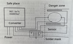
Among the electromagnetic flowmeter explosion-proof products, there are the explosion-proof products according to the positive pressure type explosion-proof method Exp mentioned above, the converter housing, and the explosion-proof sensor housing that meets the explosion-proof method Ex d standard, and the sand-filled, Explosion-proof type of encapsulated sensor. More is to install the converter in a safe area where there is no explosive gas and material, isolate it by a safety explosion-proof barrier, and connect it to the sensor installed in the explosive area (see Figure 3-41). Due to the energy limitation of the safety barrier, the voltage, and currently sent to the dangerous site are limited. Zener Z is used to limit the voltage so that the voltage at both ends of the Zener is always kept below the safe voltage: the resistor R is used to limit the current, and the appropriate selection of the resistance value can limit the loop current within the safe current limit; the function of the fuse F It is to prevent the long-term large current flowing through the Zener tube from being blown and causing the loop voltage limiting failure. In order to ensure the safety of the circuit voltage limit, the fuse must be a high-speed fuse type.
The fusing speed is 10 times faster than the Zener tube breakdown. As shown in Figure 3-41, the circuit uses three zener tubes in redundant parallel connection, which can ensure the normal operation of the safety barrier. If there is one fault or two faults, the output energy can be reliably limited within the range specified by the safety parameters. , So as to meet the requirements of ia-level intrinsic safety.
The sensor can be designed and manufactured according to relevant standards such as positive pressure type explosion-proof method Ex p, isolation type explosion-proof method Ex d, increased safety type explosion-proof method Ex e, encapsulation type explosion-proof method Ex m, and sand-filled explosion-proof method Ex q.

