This essential guide provides instrument fitters and engineers with the foundational knowledge, critical installation steps, and troubleshooting tips needed to master instrument tube fittings, focusing on the commonly used compression and threaded types.
I. Fundamentals of Instrument Fittings
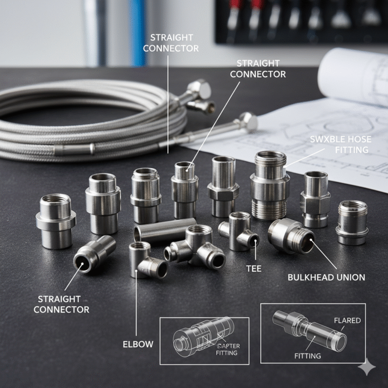
1. Common Fitting Types
Connectors: Straight connectors, bulkhead unions, tees, and elbows.
Specialized Types: Swivel nut fittings, joint fittings, plugs, and adapter fittings (transition fittings).
Classification by Connection: Hard pipe fittings (flared, compression, and welded) and flexible hose fittings (crimped).
2. Understanding Pipe Thread Standards
Pipe threads are primarily used for pipe connection, ensuring a tight fit between the internal and external threads, which can be straight or tapered.
| Abbreviation | Full Name/Standard | Angle | Key Characteristic |
| NPT | National (American) Pipe Thread | 60 | American standard 60 taper pipe thread. |
| PT | Pipe Thread (British) | 55 | British standard 55 sealing conical pipe thread. |
| G | Non-Sealing Pipe Thread | 55 | 55 non-sealing pipe thread, denoted by G for cylindrical thread. |
3. Key Differences: Metric vs. Imperial Threads
The biggest difference lies in how they are measured:
Metric Threads: Expressed using pitch. The tooth profile is a 60 equilateral triangle.
Imperial/American Threads: Expressed by the number of threads per inch (TPI). Imperial threads have a 55 isosceles tooth profile, while American threads are 60.
Industry Note: Thread dimensions like 1/4, 1/2, and 1/8 refer to the thread diameter in inches. Industry professionals often use “fen” (parts) for inches, where 1 inch equals 8 fen. Thus, 1/4 inch is 2 fen.
4. Special Type: Flexible Conduit Connectors
Purpose: Used as protective tubing for electric wires, cables, and automation instrument signal lines.
Structure & Material: Typically stainless steel with embedded single- or double-buckle structures.
Applications: Ultra-small bore conduit (3mm to 25mm inner diameter) protects sensing lines for precision optical scales and industrial sensors.
II. Focus: Compression Tube Fittings
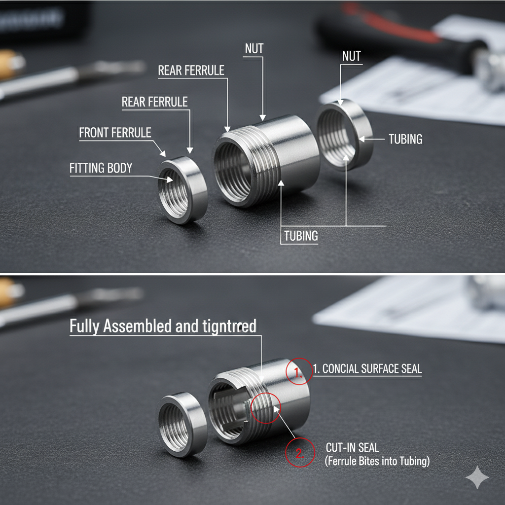
1. Structure
A standard compression tube fitting consists of a nut, ferrule(s) (sometimes only one), the fitting body, and the tube.
2. Sealing Principle
The seal is achieved when the ferrule (or rear ferrule) is pressed forward by the tightening of the nut. The front ferrule is squeezed into the conical bore of the fitting body and against the tube. This forms two seals:
Conical Surface Seal: Formed by the contact between the ferrule’s outer tapered surface and the body’s tapered bore.
Cut-in Seal: The inner cutting edge of the ferrule embeds itself into the outer wall of the steel tube, creating a closed ring groove.
III. Critical Installation Procedures
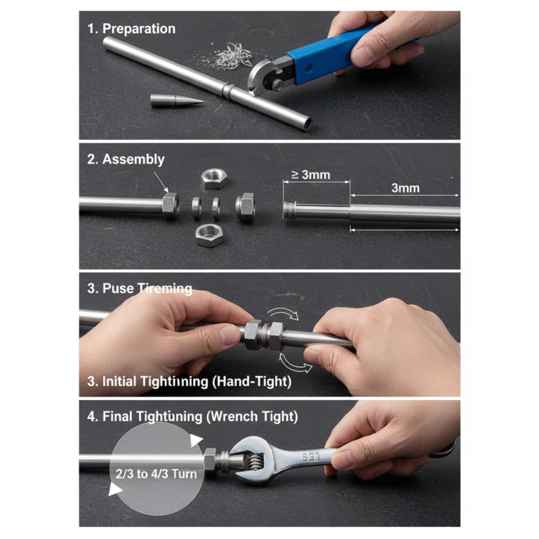
1. Compression Tube Fittings Installation
Preparation: Remove burrs and metal chips from the inner and outer ends of the tube, and clean any anti-rust agents or debris from the tube and fitting26. Ensure the tube end is round.
Assembly: Slide the nut, then the ferrule(s) onto the tube. The ferrule’s front cutting edge (small diameter end) must be positioned at least 3mm from the tube end. Insert the tube into the fitting body’s cone until it bottoms out.
Initial Tightening: Hand-tighten the nut slowly while rotating the tube until the tube stops moving.
Final Tightening: From the point the tube stops, tighten the nut for an additional 2/3 to 4/3 turn (approximately 1 to 1.3 turns).
2. Quick Connect Couplings Installation & Disassembly
| Installation Steps | Disassembly Steps |
1. Apply appropriate thickness of PTFE (Teflon) tape to the threads of the quick coupling. | 1. Check First: Ensure the medium flow through the connecting pipe has been shut off. |
2. Tighten the coupling using the correct force. | 2. Use your thumb and index finger to press the collet towards the quick coupling body. |
3. Cut the end of the tube to be inserted vertically and flat using a cutter. | 3. While holding the collet pressed, pull the tube straight out with your other hand. |
4. Insert the cut tube end firmly into the coupling until it reaches the bottom. | |
5. Verification: Gently tug on the tube to confirm the connection is secure; it should not detach. |
IV. Common Fitting Headaches & Solutions
Mixing Standards: Never interchange NPT, PT, or G threads, as the different angles (55vs60) will lead to leaks.
Poor Tubing Prep: Failing to cut the tube end perfectly square/perpendicular will prevent the ferrule from seating evenly, leading to a leak. Always remove all burrs.
Incorrect Torque: The 2/3 to 4/3 turn rule is crucial for compression fittings. Undertightening leads to leaks, while overtightening damages the ferrule and tube integrit