Q: What is Faraday’s law of electromagnetic induction?
A: When any conductor moves at right angles in a magnetic field, a voltage is induced in it, and this voltage is proportional to the speed of the conductor.
Q: What is the Lorentz force? How do we get the electric field force?
A: The force on a moving charge in a magnetic field is called the Lorentz force. When a conductive medium passes through a magnetic field, it will be affected by the Lorentz force. Under the action of the Lorentz force, positive and negative charges flow in corresponding directions, forming a potential difference, thus generating an electric field.
Q: How does the electromagnetic flowmeter work?
A: The measurement principle of the electromagnetic flowmeter is based on Faraday’s law of electromagnetic induction: When a conductive liquid cuts magnetic lines of force in a magnetic field, an induced potential is generated in the conductor, and the induced electric heat E is: E=KBVD, where: k is the instrument constant; B is the magnetic induction intensity; V is the average flow velocity in the measured pipe section; D is the inner diameter of the measured pipe section. When measuring flow, the conductive liquid flows at a speed; V is the magnetic field that flows perpendicular to the flow direction. The flow of the conductive liquid induces a voltage that is proportional to the average flow velocity. The induced voltage signal is detected by two or more electrodes that are in direct contact with the liquid, and is sent to the converter through a cable for intelligent processing, LCD display or conversion into a standard signal 4-20mA output.
Q: What are the requirements of electromagnetic flow on the medium?
A: The fluid that uses electromagnetic flowmeter to measure flow must be conductive. Therefore, electromagnetic flowmeter cannot be used to measure the flow of non-conductive gas, steam, oil, acetone and other materials.
There are two common faults in the operation of electromagnetic flowmeters: one is the fault of the instrument itself, that is, the fault caused by damage to the instrument structure or components; the other is the fault caused by external reasons, such as improper installation, flow changes, deposition and scaling, etc. We will discuss these two types of faults.
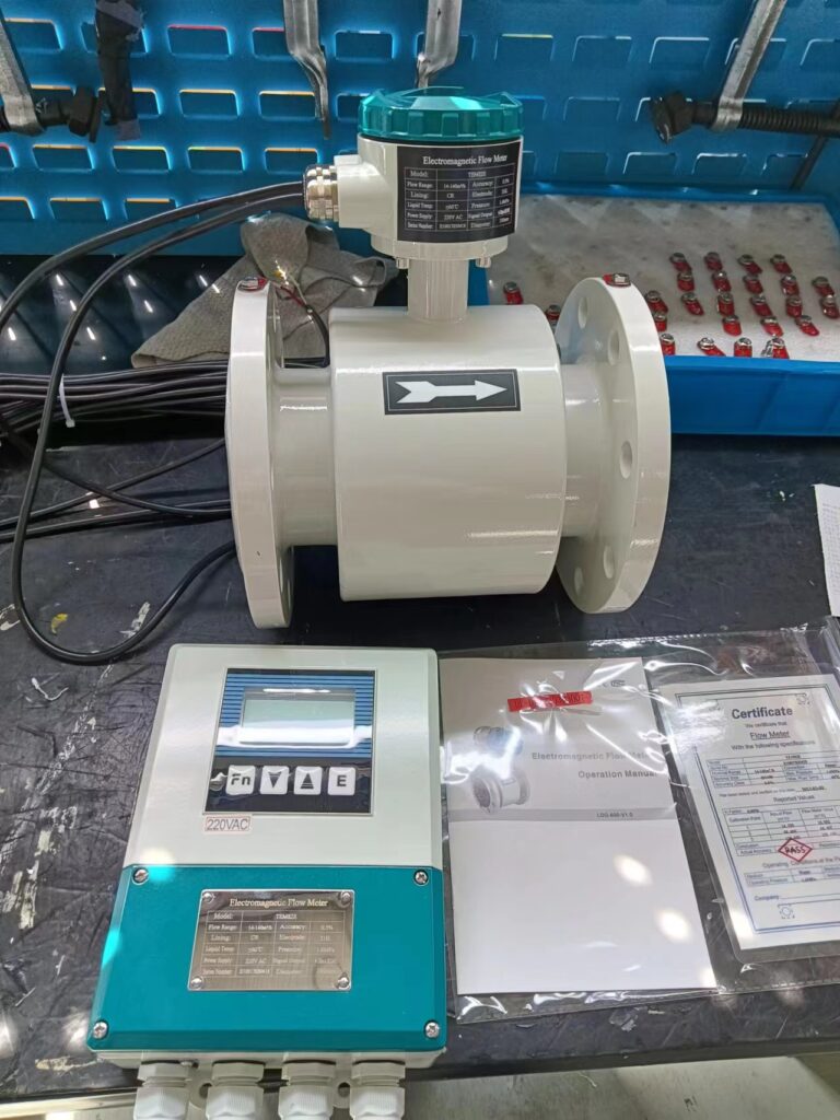
Q: Analysis of the reasons why the instrument has no flow signal output:
This type of fault is relatively common during use, and the reasons are generally:
(1) The power supply of the instrument is abnormal;
(2) The cable connection is abnormal;
(3) The liquid flow condition does not meet the installation requirements;
(4) The sensor parts are damaged or there is an adhesion layer on the measuring inner wall;
(5) The converter components are damaged.
A: (1) Confirm that the power supply has been connected, check whether the output voltage of each line of the power circuit board is normal, or try to replace the entire power circuit board to determine whether it is good or bad.
(2) Check whether the cable is intact and the connection is correct.
(3) Check the direction of liquid flow and whether the liquid in the pipe is full. For electromagnetic flowmeters that can measure in both directions, if the direction is inconsistent, although the measurement can be made, the set forward and reverse directions of the displayed flow are inconsistent and must be corrected. If the workload of removing the sensor is large, you can also change the direction of the arrow on the sensor and reset the display instrument symbol. The pipe is not full of liquid, which is mainly caused by improper installation of the sensor. Measures should be taken during installation to avoid causing the pipe to be full of liquid.
(4) Check whether the inner wall electrode of the transmitter is covered with a liquid scaling layer. For the measurement liquid that is easy to scale, it should be cleaned regularly.
(5) If it is determined that the fault is caused by damage to the converter components, the damaged components can be replaced.
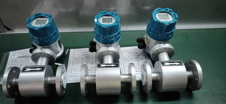
Q: Analysis of the causes of output value fluctuation: This type of fault is mostly caused by the influence of the measuring medium or the external environment. The fault can be eliminated by itself after the external interference is eliminated. In order to ensure the accuracy of the measurement, this type of fault should not be ignored. In some production environments, due to the large vibration of the measuring pipe or liquid, the circuit board of the flow meter will become loose, which may also cause the output value to fluctuate.
A: (1) Confirm whether it is caused by process operation. The fluid is indeed flowing. At this time, the flow meter only reflects the flow condition truthfully. After the pulsation ends, the fault can be eliminated by itself.
(2) Electromagnetic interference caused by external stray currents. Check whether there are large electrical appliances or electric welding machines working in the instrument operating environment, and make sure that the instrument is grounded and the operating environment is good.
(3) When the pipeline is not full of liquid or there are bubbles in the liquid, both are caused by process reasons. At this time, you can ask the process personnel to confirm. After the liquid is full or the bubbles are calmed, the output value can return to normal.
(4) The transmitter circuit board is a plug-in structure. Due to the large vibration of the measuring pipe or liquid on site, the power board of the flow meter is often loose. If it is loose, the flow meter can be disassembled and the circuit board can be re-fixed.

Q: The flow measurement value does not match the actual value
Cause analysis:
(1) Is the transmitter circuit board intact?
(2) When the liquid flow rate is too low, the measured liquid contains tiny bubbles, which rise and gradually gather above the pipe, and the liquid flow area changes. When there is a lot of gas, interference signals will be generated, affecting the measurement accuracy; (3) The signal cable is not connected properly or the insulation performance of the cable decreases during use, causing inaccurate measurement;
(4) The parameter setting value of the converter is inaccurate.
A: (1) Check whether the transmitter circuit board is intact. If the junction box is flooded or corroded by the corrosive measured liquid, the electrical performance may decrease or be damaged. In this case, the circuit board should be replaced.
(2) Ensure that the flow rate of the measured liquid in the pipeline is above the minimum flow limit value so that the transmitter can work normally.
(3) Check whether the signal cable connection and the insulation performance of the cable are intact. If the signal cable is loose, reconnect it; if the insulation of the cable does not meet the insulation requirements, a new cable needs to be replaced.
(4) Reset the converter setting value and calibrate the zero point and full scale value of the converter.

Q: Output signal exceeds full scale
Cause analysis: (1) Signal cable wiring error or cable disconnection; (2) Converter parameter settings are incorrect; (3) Converter and sensor models do not match.
A: (1) Check whether the signal circuit is connected normally. If the signal circuit is disconnected, the output signal will exceed the full scale value. At this time, the signal cable needs to be reconnected correctly. At the same time, check whether the insulation performance of the cable is intact. If it does not meet the requirements, replace it with a new cable. (2) Check the converter parameter settings and zero point and full scale in detail to see if they meet the requirements. (3) If the converter and sensor models are not matched, you need to contact the manufacturer for replacement.

Q: Analysis of the causes of unstable zero point:
(1) The pipe is not filled with liquid or there are bubbles in the liquid.
(2) Subjectively believe that there is no flow in the pipe pump liquid, but there is actually a small flow.
(3) Liquid-related reasons (such as poor uniformity of liquid conductivity, electrode contamination, etc.).
(4) Signal circuit insulation degradation.
A: (1) The pipe is not filled with liquid or there are bubbles in the liquid, which are both process reasons. At this time, you should ask the process personnel to confirm. After the process is normal, the output value can return to normal.
(2) There is a small amount of flow in the pipe, which is not a fault of the electromagnetic flowmeter.
(3) If impurities are deposited on the inner wall of the measuring tube or scale is formed on the inner wall of the measuring tube, or the electrode is contaminated, zero point changes may occur. At this time, it must be cleaned; if the zero point change is not large, you can also try to re-zero.
(4) Due to the influence of environmental conditions, dust, oil, etc. may enter the meter housing. Therefore, it is necessary to check whether the insulation of the electrode part is degraded or damaged. If it does not meet the insulation requirements, it must be cleaned.

Q: What are the precautions for installing electromagnetic flowmeters?
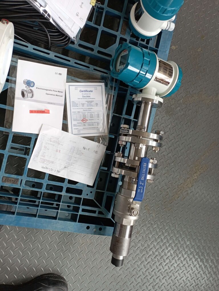
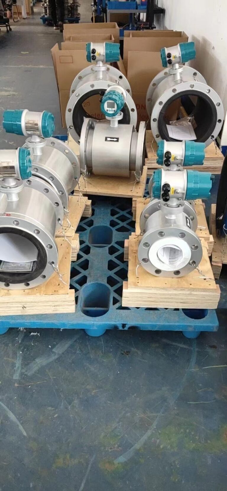
A: ① For electromagnetic flowmeters, especially small flowmeters less than DN100mm (4”), the stress-bearing part during transportation must not be anywhere on the signal transmission, but on the body of the flowmeter.
② Select the installation position as required, but no matter how the position changes, the motor shaft must remain basically horizontal.
③ The measuring tube of the electromagnetic flowmeter must be completely filled with medium at all times.
④ During installation, it should be noted that the positive and negative directions of the flow should be consistent with the flow direction of the medium.
⑤ During installation, ensure that there is enough space between the bolts and nuts and the pipe flange for easy loading and unloading.
⑥ For the measurement of seriously polluted fluids, the electromagnetic flowmeter should be installed on the bypass.
⑦ Large electromagnetic flowmeters with DN greater than 200mm (8”) should use a transfer tube to ensure the axial offset of the docking flange for easy installation.
⑧ The minimum straight pipe section requirement is 5DN on the upstream side and 2DN on the downstream side.
⑨ Avoid installation in places with strong electromagnetic fields.
⑩ The ambient temperature requirements are: when the product temperature is less than 60 degrees, the ambient temperature is less than 60 degrees; when the product temperature is greater than 60 degrees, the ambient temperature is less than 40 degrees.

Q: What are the structures of electromagnetic flowmeters and what are their functions?
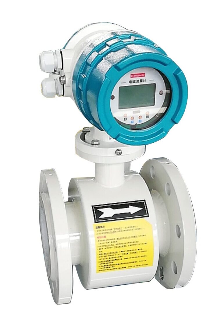
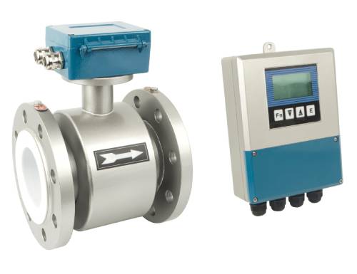
A: The structure of electromagnetic flowmeters is mainly composed of magnetic circuit system, measuring conduit, electrode, shell, lining and converter.
① Magnetic circuit system: Its function is to generate a uniform DC or AC magnetic field. The DC magnetic circuit is realized by permanent magnets. Its advantage is that the structure is relatively simple and less disturbed by the AC magnetic field, but it is easy to polarize the electrolyte liquid passing through the measuring conduit, so that the positive electrode is surrounded by negative ions and the negative electrode is surrounded by positive ions, that is, the polarization phenomenon of the electrode, and the internal resistance between the two electrodes increases, which seriously affects the normal operation of the instrument. When the diameter of the pipeline is large, the permanent magnet is also large, bulky and uneconomical, so the electromagnetic flowmeter generally uses an alternating magnetic field, and is excited by a 50Hz power frequency power supply.
② Measuring conduit: Its function is to allow the conductive liquid to pass through. In order to make the magnetic flux be shunted or short-circuited when the magnetic lines of force pass through the measuring conduit, the measuring conduit must be made of non-magnetic, low-conductivity, low-thermal conductivity and mechanically strong materials. Non-magnetic stainless steel, fiberglass, high-strength plastic, aluminum, etc. can be selected.
③ Electrode: Its function is to lead out the induced potential signal proportional to the measured value. The electrode is generally made of non-magnetic stainless steel and is required to be flush with the lining so that the fluid can pass through without obstruction. Its installation position should be in the vertical direction of the pipeline to prevent sediment from accumulating on it and affecting the measurement accuracy.
④ Shell: Made of ferromagnetic material, it is the outer cover of the excitation coil of the distribution system and isolates the interference of the external magnetic field.
⑤ Lining: There is a complete electrical insulation lining on the inner side of the measuring conduit and the flange sealing surface. It is in direct contact with the measured liquid. Its function is to increase the corrosion resistance of the measuring conduit and prevent the induced potential from being short-circuited by the metal measuring conduit wall. The lining materials are mostly corrosion-resistant, high-temperature-resistant, and wear-resistant polytetrafluoroethylene plastics, ceramics, etc.
⑥ Converter: The induced potential signal generated by the flow of liquid is very weak and is greatly affected by various interference factors. The role of the converter is to amplify the induced potential signal and convert it into a unified standard signal and suppress the main interference signal. Its task is to convert the induced potential signal Ex detected by the electrode into a unified standard DC signal after amplification.
