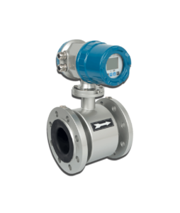
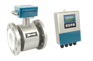
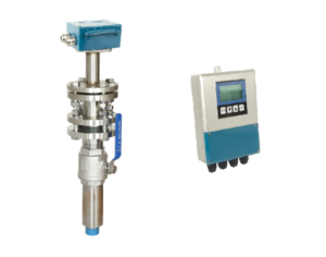
We call the electromagnetic flow sensor used for measuring closed pipes filled with the fluid medium as general-purpose sensors.
The general sensor product caliber can range from 1mm to 3m. Such a wide range of different calibers brings some differences in the structure and performance of the flowmeter, and the difference in performance is mainly reflected in the measurement accuracy. Table 3-6 lists the measurement accuracy grade indexes of the electromagnetic flowmeters of modern typical general-purpose sensors.
| Diameter | |
| Classification | Size/mm |
| Micro | 1~15 |
| Small and medium | 20~600 |
| large-scale | 700~3000 |
From the perspective of fluid mechanics, the fluid flow state in a small-diameter microsensor may be turbulent or laminar, and most of it is in a laminar flow state at low flow rates. The diameter of the measuring tube is small, and the change in the velocity distribution caused by the roughness of its inner wall has a relatively large impact on the measurement.
From the perspective of product manufacturing, it is difficult to ensure the consistency of the size of the micro-diameter sensor processing, and the assembly accuracy of the electrode circuit is difficult to control, especially since the zero point value is relatively large.
The reason for the large zero-point amplitude is that the designed and manufactured sensor produces the same signal amplitude per 1m/s flow rate, the small magnetic induction intensity is high, and the relative change rate of the electrode lead loop area is larger than that of the small and medium-sized sensor. Therefore, according to the law of electromagnetic induction, the quadrature interference (in-phase interference) of the micro-small induction will be larger than that of the small and medium-sized diameter sensor. Second, the small diameter of the electrode has a small diameter and high signal internal resistance, which often causes high common-mode interference.

This requires better grounding (fluid connection) during application. Combining the above-mentioned influencing factors reduces the measurement accuracy of micro-diameter gauges.
From the perspective of fluid mechanics, the fluid flow state in a small-diameter microsensor may be turbulent or laminar, and most of it is in a laminar flow state at low flow rates.
The diameter of the measuring tube is small, and the change in the velocity distribution caused by the roughness of its inner wall has a relatively large impact on the measurement.
From the perspective of product manufacturing, it is difficult to ensure the consistency of the size of the micro-diameter sensor processing, and the assembly accuracy of the electrode circuit is difficult to control, especially since the zero point value is relatively large.

The reason for the large zero-point amplitude is that the designed and manufactured sensor produces the same signal amplitude per 1m/s flow rate, the small magnetic induction intensity is high, and the relative change rate of the electrode lead loop area is larger than that of the small and medium-sized sensor.
Therefore, according to the law of electromagnetic induction, the quadrature interference (in-phase interference) of the micro-small induction will be larger than that of the small and medium-sized diameter sensor.
Second, the small diameter of the electrode has a small diameter and high signal internal resistance, which often causes high common-mode interference. This requires better grounding (fluid connection) during application. Combining the above-mentioned influencing factors reduces the measurement accuracy of micro-diameter gauges.

For large sensors, although the designed and manufactured sensors have the same flow rate signal amplitude per 1m/s as small and medium-sized sensors, their magnetic induction intensity is lower. However, the electrode lead loop area of a large sensor is relatively large, and its relative change rate may also be relatively large.
Therefore, the quadrature interference and the in-phase phase are relatively large, that is, the zero value is relatively high. More importantly, the eddy current of the large-diameter sensor measuring tube is large, and the iron loss current is also large, and the signal-to-noise ratio will decrease, which is an important reason for the decreased inaccuracy. Furthermore, it is difficult to meet the length requirements of the straight pipe section before and after the instrument using the installed large-diameter sensor.
In other words, it is difficult to ensure the axial symmetry of the flow velocity distribution in the sensor. In short, as with micro-mini, due to fluid measurement principles and structural problems, it also affects the improvement of the measurement accuracy of large-scale sensors.
The electrode structure of the miniature sensor can only be externally inserted, and the materials in the village can only use injection-molded fluoroplastics and industrial ceramics.
The flowmeters of large sensors are generally used to measure water or sewage, and the requirements for the corrosiveness, temperature, pressure, and abrasion of the medium are relatively low. Therefore, the lining material is usually rubber or polyurethane rubber, and the electrode material is generally made of molybdenum-containing acid-resistant steel (such as 0C17Ni14Mo2 or 316L).
