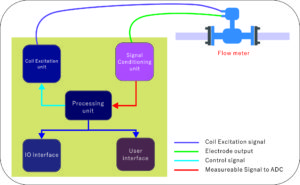
The following diagram depicts the architecture of the electromagnetic flow meter.

The flow tube
The flow tube houses the terminals in direct contact with the moving conductive fluid and field coil. The electrode contained here is an essential element as it picks up the voltage in the fluid. Electrode elements have different options that feature different corrosion rates, temperature drift, and potential terminal characteristics like SS and titanium. However, this selection greatly relies on the durability and type of fluid being measured.
Coil excitation system
This unit produces an electrical current that cuts the field wires according to the processing unit’s charge signal to produce the controlled magnetic field.
Signal conditioning unit
The unit changes the flow tubing terminal output to a notable measurable signal to measure the flow.
Processing unit
The processing unit is the center of the electromagnetic current meter. This unit generates the control signal for loop excitation. Moreover, the unit gives the final reading of currents to user interfaces and IO by working on the conditioning unit’s signal unit with different mathematical and statistical formulas.
IO interface
The interface gives support for the flow of information to the current outer device. In communicating with external devices, the interfaces utilize the various output formats like voltage output, pulse output, RS485/RS232 serial communication, and relay output. A flow meter also supports the interfacing of transistors or sensors, and external transmitters as a valued added option.
User interface
A user interface such as keypads, LEDs, and LCDs offers an easy manual operation editing, setting the flow meter arrangement at the field.
Power supply unit
The power supply unit offers a constant supply of energy by determining the quality of the measurements. Either a battery or an AC source powers the magmeter. For a long battery life for Magmeters, it is necessary to use a component selection and smart power management.
