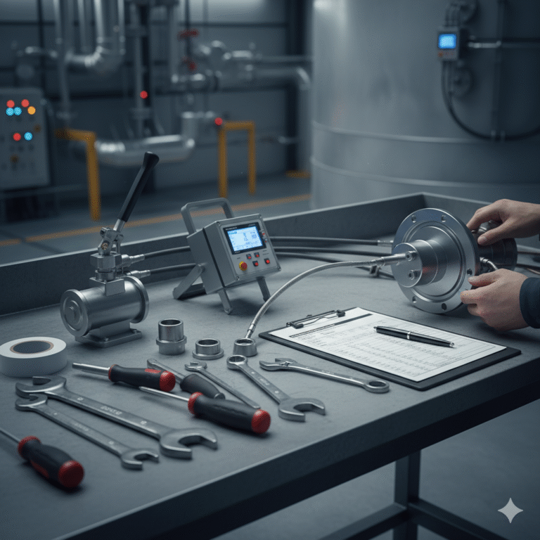
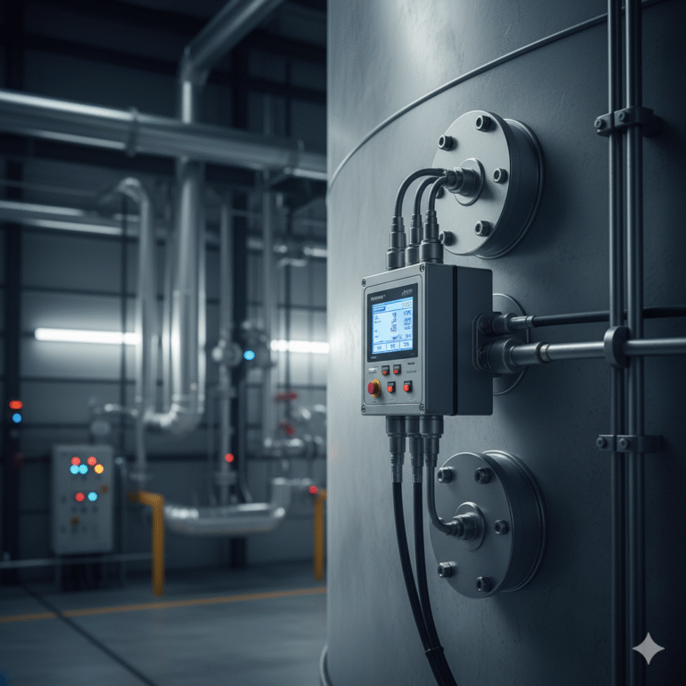
Pressure calibration for the double flange level transmitter is a crucial step to ensure measurement accuracy. Below are the detailed steps and precautions for the calibration process:

Calibration Steps
1. Pre-calibration Preparation
Tools and Equipment: Prepare a standard pressure source (such as a manual pressure pump with higher accuracy than the level transmitter), a precision pressure gauge (as a reference standard), connecting hoses, adapters (compatible with the transmitter flanges), wrenches, etc. Also, prepare a record sheet to log calibration data.
Instrument Inspection: Inspect the double flange level transmitter for any damage, ensure the diaphragm is intact, check the capillary tube for any cracks or flattening. Verify the transmitter’s range and accuracy parameters to facilitate the calibration process.
Installation and Connection: Connect the standard pressure source to the positive pressure side (lower flange) of the level transmitter using the connecting hose. The negative pressure side (upper flange) should be vented to the atmosphere (or connected to a corresponding pressure source if there is pressure in the negative side during actual use). Ensure all connections are tight to prevent leaks.
2. Zero Point Calibration
Apply Zero Pressure: Close the valve to the transmitter’s pressure input, ensuring the positive pressure side reads zero (atmospheric pressure). Wait briefly for the transmitter to stabilize.
Adjust Zero Point: Monitor the transmitter’s output signal (e.g., 4-20mA or corresponding voltage). If the output does not match the zero point value (typically 4mA or the lower voltage), adjust the zero point using the transmitter’s zero-point adjustment mechanism (e.g., potentiometer or hand controller).
3. Span Calibration
Calculate Pressure Value: Based on the transmitter’s range and the medium’s density, calculate the corresponding pressure at full scale. For example, for a water-based transmitter with a 0-10m range, the full-scale pressure is calculated as: Pressure = Density × Gravity × Range = 1000 kg/m³ × 9.8 m/s² × 10 m = 98,000 Pa.
Apply Pressure: Slowly open the pressure valve and gradually apply pressure to the positive pressure side of the transmitter, approaching the calculated full-scale pressure. Apply pressure gently to prevent shock loads from damaging the transmitter.
Adjust Span: When the full-scale pressure is reached, observe the output signal. If the output does not match the full-scale value (typically 20mA or the upper voltage), adjust the span using the span adjustment mechanism.
Intermediate Calibration: Select at least two intermediate pressure points (e.g., 25%, 50%, 75% of the full range), apply pressure, and adjust the output signal as per the span calibration method to ensure the transmitter’s accuracy across its entire range.
4. Hysteresis (Backlash) Calibration
Pressure Increase Calibration: Start from zero pressure, slowly increase the pressure to full scale, and record the output signal at each calibration point.
Pressure Decrease Calibration: After reaching full scale, gradually reduce the pressure to zero and record the output signal at each calibration point. Compare the output signals from the increasing and decreasing pressure processes. The difference is called the hysteresis. It should meet the transmitter’s accuracy requirements.
5. Calibration Completion
De-pressure: After completing the calibration, slowly open the pressure release valve to reduce the pressure to zero. Disconnect the pressure source and hoses.
Record and Report: Organize the calibration data and fill out the calibration report, including the transmitter’s basic information, calibration points, pressure values, output signal values, and hysteresis. Assess whether the transmitter is qualified based on the results. If not, analyze the causes and take corrective actions.

Precautions
Safety Protection: During calibration, high pressure may be involved. Always take necessary safety precautions to avoid injuries from sudden pressure release. If flammable or explosive materials are present at the site, ensure that the calibration process does not trigger safety hazards.
Temperature Effects: The capillary tube of the double flange level transmitter is filled with silicone oil or similar media, and temperature changes can affect its volume and pressure transmission. Try to maintain a stable temperature environment during calibration. If temperature variations are significant, account for this effect and make appropriate corrections.
Leakage Check: After connecting the pressure source and during calibration, always check the connection points for leaks. If any leaks are detected, immediately stop the calibration, find and fix the leak, then restart the calibration process, as leaks can affect the calibration results.
Operational Guidelines: When operating the pressure source, apply pressure slowly and steadily to avoid sudden pressure changes that could damage the transmitter. Follow the manual’s instructions when adjusting the zero point and span to ensure proper calibration.
Calibration Frequency: It is recommended to perform pressure calibration at least once a year. For transmitters that are used frequently or in critical applications, the calibration interval should be shorter to ensure measurement accuracy.
