Introduction The correct installation of the magnetic flip plate level gauge is crucial for its normal operation and accurate measurement, especially regarding the installation of the magnetic float, which requires strict adherence to operational norms. Below is a detailed discussion on the proper installation of the magnetic float in a magnetic flip plate level gauge:
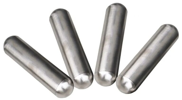
I. Installation Direction of the Magnetic Float When installing the magnetic flip plate level gauge, the installation direction of the magnetic float is very easy to get wrong.
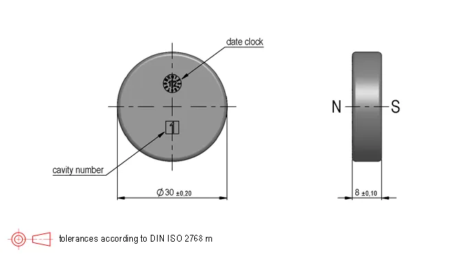
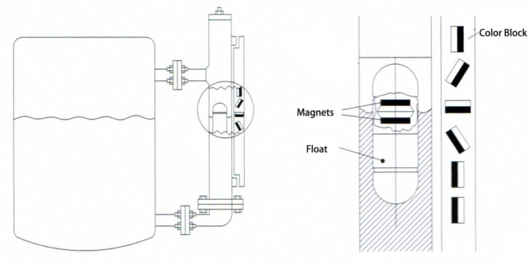
The magnetic float contains a magnet, which is either annular or made of two magnetic poles combined back-to-back, presenting as either the south or north pole externally. The float is typically cylindrical, with one end containing the magnet and the other end not.
During installation, the magnetic end must be placed upwards into the magnetic flip plate level gauge.
There are two ways to determine the magnetic properties of the float: one is by testing with a magnet or a ferromagnetic object, and the other is by following the markings on the float made at the factory to indicate the magnetic direction for easy installation.
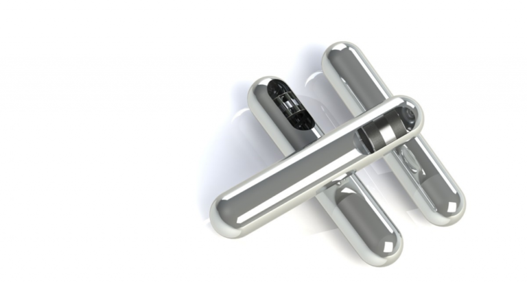
II. Steps for Installing the Magnetic Float
Preparation Stage:
- Remove the float chamber flange or the bottom drain flange.
- Insert the float according to the direction of the arrow (with the magnetic steel located in the upper half) or insert the heavier end of the float first into the float chamber.
- Reattach the float chamber flange, ensuring the seal is properly placed and the bolts are evenly tightened.
Testing Stage:
- Seal the lower flange of the level gauge and slowly introduce clean water into the float chamber through the upper connection flange.
- If the indicator shows a level reading without any jumps or interruptions and moves smoothly back and forth three times, the float is working properly.
Calibration Stage:
- For tracking-type indicators, use a plastic strip to push the indicator float to couple it with the magnetic float inside the chamber (for indicator type gauges).
- Alternatively, use a magnetic bar to attract the indicator from the bottom to the top to ensure it displays correctly.
III. Precautions for Installing the Magnetic Float
Vertical Installation:
- The magnetic flip plate level gauge must be installed vertically to ensure that the magnetic float moves freely up and down inside the main guide tube.
Avoid Interference:
- There should be no magnetic materials near the magnetic flip plate level gauge as they could interfere with its normal functioning.
- Also, ensure that no solid impurities or magnetic substances enter the main guide tube to prevent the float from getting stuck or reducing its buoyancy.
Install a Valve:
- A stop valve should be installed between the measured tank and the level gauge to allow the liquid to be cut off when cleaning the level gauge.
Pressure Testing:
- If the test pressure exceeds 1.25 times the working pressure of the instrument, the float should be removed from the chamber.
- After the hydrostatic test passes, the float can be reinserted, and a gas-tightness test not exceeding 1.05 times the working pressure can be conducted.
Float Protection:
- To prevent the magnetic float from sliding inside the chamber during transportation, it is secured to the chamber with a nylon band or clip before leaving the factory.
- Before installation, the user needs to open the lower flange or the lower liquid outlet valve, place the float inside the chamber, and ensure that the magnetic end with the arrow and heavier side is facing upwards.
- For magnetic floats lined with the magnetic flip plate level gauge, the float must not be inserted through the top sealed flange to avoid damaging the inner lining and compromising its anti-corrosion properties when the float suddenly falls to the bottom.
Proper Operation:
- When putting the level gauge into operation, first open the upper liquid inlet valve, then slowly open the lower guide valve to allow the medium to gradually enter the main guide tube.
- This prevents the medium from rushing into the float too quickly, causing excessive vibrations that could disable or disarrange the magnetic flip column.
IV. Post-Installation Inspection and Commissioning
Calibrate the Magnetic Flip Column:
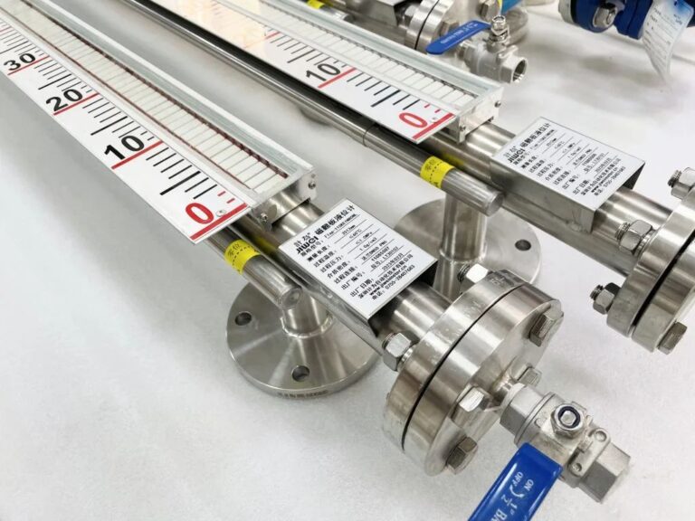
- After the level gauge installation is complete, use the calibration magnet to guide the flip column once, ensuring that the area below zero shows red and the area above zero shows white.
Check the Display:
- Observe if the magnetic red and white balls are flipping correctly, then close the lower guide valve, open the drain valve, and let the liquid level in the main guide tube drop. Repeat this process three times. If the readings are correct, the gauge is ready for use (except for special liquids like corrosive substances).
Periodic Maintenance:
- Regularly clean the magnetic float and remove any impurities in the main guide tube based on the characteristics of the medium.
- Additionally, check and clean the display panel periodically to ensure it remains clear and unobstructed.
Conclusion In summary, the correct installation of the magnetic float in a magnetic flip plate level gauge requires strict adherence to the operational guidelines, including the correct installation direction, steps, precautions, and post-installation inspection and calibration. Only by following these procedures can accurate measurement and stable operation of the magnetic flip plate level gauge be ensured.
