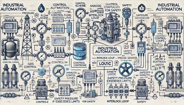
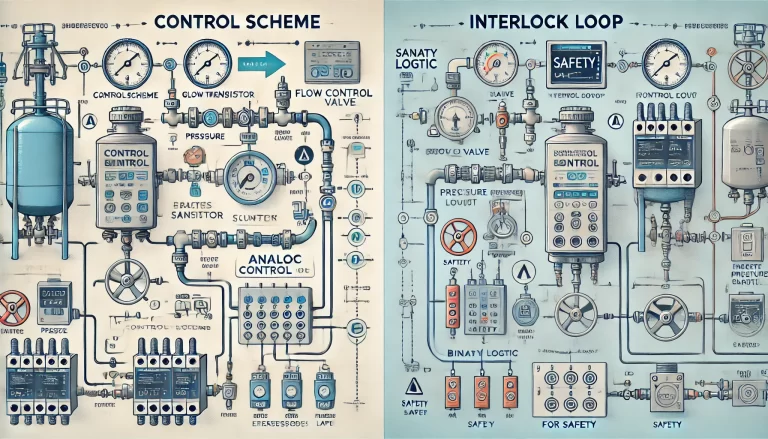
In industrial automation and process control systems, the terms “control scheme” and “interlock loop” are often used, but they refer to different aspects of a system’s logic and safety design. Understanding their differences is important for proper system design, operation, and communication.
1. Control Scheme
A control scheme (or control strategy) is the overall plan or logic that defines how a system or process is controlled to achieve the desired operational objectives. It includes various control loops and logic structures designed to maintain process variables such as pressure, temperature, flow, and level within defined ranges.
Key Features:
- High-level concept that outlines how the system should function under normal operating conditions.
- Can include automatic control loops such as PID controllers, feedforward control, cascade control, etc.
- Covers both manual and automatic modes of operation.
- Addresses normal process control, optimization, and efficiency.
- May involve multiple instruments, actuators, and control logic programmed in PLC, DCS, or other control systems.
Example: In a gas flow control system, the control scheme may include:
- A pressure transmitter to measure upstream pressure.
- A flow control valve to regulate gas flow.
- A PID controller to maintain a target flow rate by adjusting the valve based on real-time feedback.

2. Interlock Loop
An interlock loop is a specific part of the control logic that ensures safe operation of equipment and prevents hazardous conditions. Interlocks are typically binary (on/off) logics that prevent a machine or process from starting or continuing unless certain predefined conditions are met.
Key Features:
- Safety-focused logic, used to protect equipment and personnel.
- Typically implemented using digital input/output signals.
- Often used in emergency shutdown systems (ESD) or safety instrumented systems (SIS).
- Can be hardwired or software-based within PLCs/DCS.
- Not used for process control or optimization but rather to guarantee safety or sequence integrity.
Example: In the same gas system:
- An interlock loop may be used to automatically close the control valve if the downstream pressure exceeds a critical safety limit.
- Or, the system may prevent the startup of a gas compressor unless cooling water flow is confirmed.
3. Summary of Differences
| Category | Control Scheme | Interlock Loop |
|---|---|---|
| Purpose | Achieve process control and efficiency | Ensure safety and prevent unsafe operations |
| Scope | Broad, includes various control methods | Specific safety conditions or steps |
| Logic Type | Continuous or analog logic (e.g., PID) | Discrete / digital logic (e.g., ON/OFF) |
| Focus | Operational performance | Equipment and personnel protection |
| System | Part of overall control logic | Part of safety or interlock systems |
4. Relationship Between the Two
While different in purpose and function, interlock loops are often embedded within the overall control scheme. A complete control solution typically includes both:
- Process control loops for normal operations,
- Safety interlocks to handle abnormal or dangerous conditions.
In many projects, the control scheme document will include:
- Control narrative for each function or device,
- A description of all interlock conditions,
- Logic diagrams showing both control and interlock relationships.

Conclusion
In summary, a control scheme provides the full operational logic of a system, while interlock loops are specific protective measures built into that scheme. Understanding and clearly differentiating these terms ensures that systems are both effective in control and reliable in safety.
If you are working on a project or responding to a client inquiry, it’s important to explain both elements to show that the system is well-designed, efficient, and safe.
