Most accuracy problems come down to four buckets: installation, fluid properties, device faults, and external interference. Use the triage table below, then follow the corrective actions.
1) Rapid triage (symptom → likely cause → how to check → fix)
Symptom
Likely cause
How to check
Corrective action
Reading drifts / unstable
Not full pipe; air bubbles
Look for gurgling, intermittent zero; inspect upstream vents
Ensure full pipe; add air vent upstream; throttle valve downstream
Consistently high/low vs. reference
Wrong diameter/scale in converter
Compare converter setup vs. actual line size/flow range
Re-enter pipe ID, range; perform zero calibration (full pipe, no flow)
Intermittent spikes
Poor grounding / VFD noise
Measure ground loop; note proximity to VFDs/transformers
Separate protective grounds; ≤10 Ω; route cables away from noise sources
Near-zero on conductive service
Electrodes fouled
Inspect electrodes; look for scale/oil films
Clean with soft cloth or mild acid compatible with material
Output saturates at max
Flow exceeds range; wrong K-factor
Compare process flow vs. configured span
Increase range or use larger meter; correct configuration
Reading only at high flow
Low conductivity fluid
Check conductivity (>~5 µS/cm needed)
Switch technology (e.g., ultrasonic) or adjust process chemistry
Random dropouts
Coil/lead faults
Measure coil resistance (per datasheet, usually tens of Ω)
Repair wiring; replace sensor/coil if out of spec
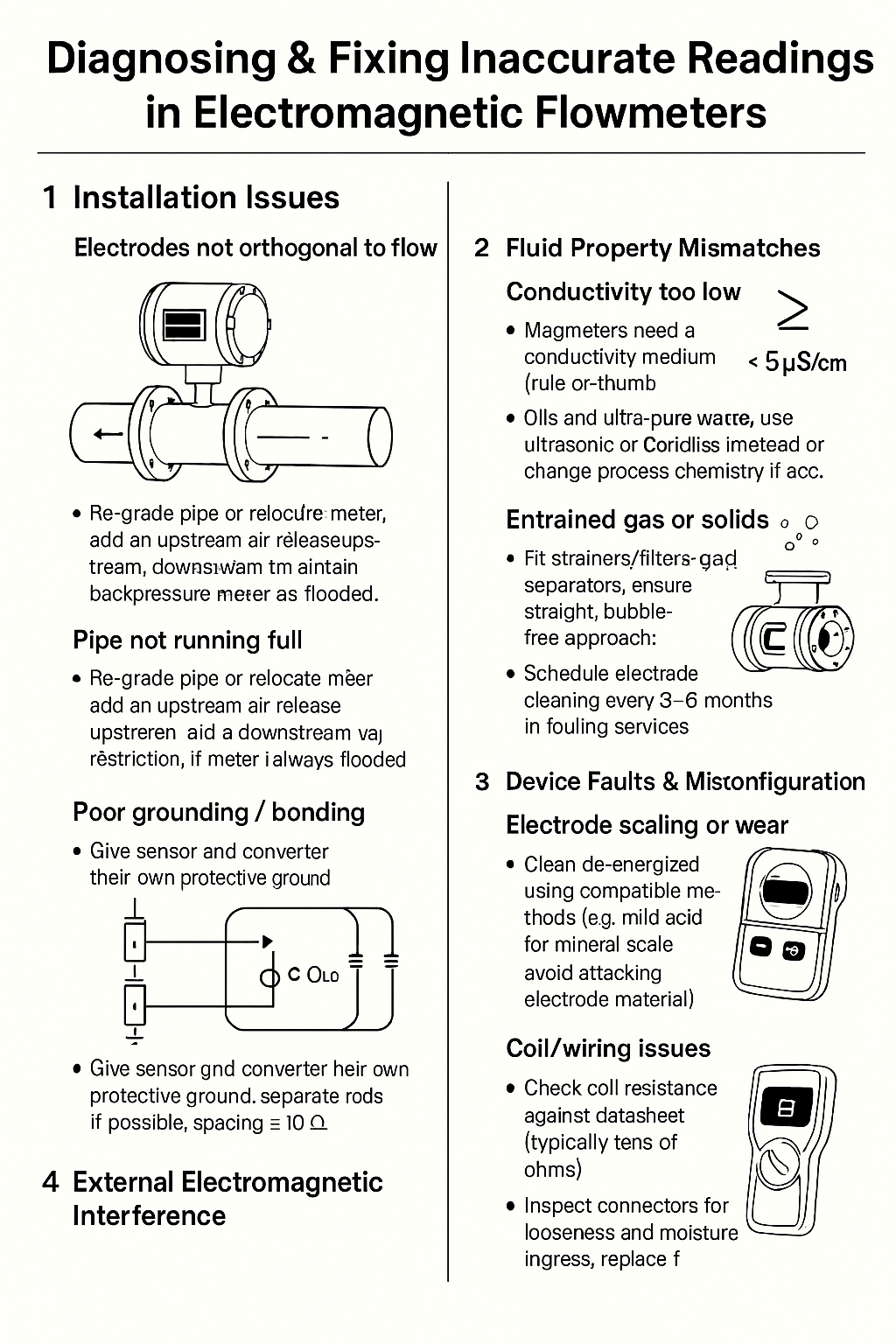
2) Installation issues (most common)
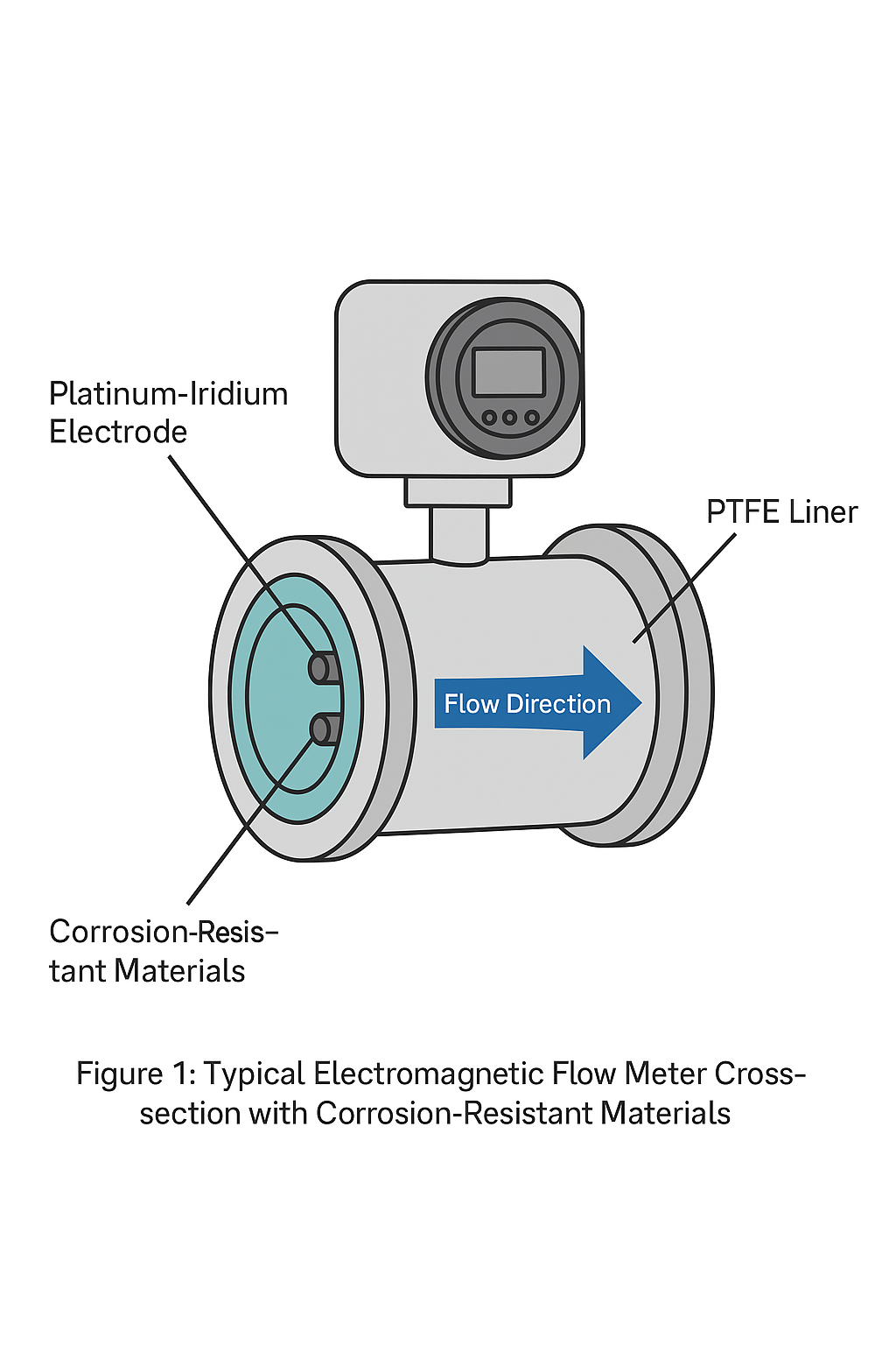
Electrodes not orthogonal to flow
Ensure the electrode axis is perpendicular to flow. On horizontal runs, keep electrodes on the horizontal centerline to avoid gas/slag accumulation. Re-align the body if needed.
Pipe not running full
Re-grade pipe or relocate meter; add upstream air release and a downstream restriction/valve to maintain backpressure so the meter is always flooded.
Poor grounding / bonding
Give the sensor and converter their own protective ground (separate rods if possible, spacing >5 m). Target ground resistance ≤10 Ω. Bond liners or grounding rings as specified.
3) Fluid property mismatches
Conductivity too low
Magmeters need a conductive medium (rule-of-thumb >~5 µS/cm). Oils and ultra-pure water may not work—use ultrasonic/Coriolis instead or change process chemistry if acceptable.
Entrained gas or solids
Fit strainers/filters and gas separators; ensure straight, bubble-free approach. Schedule electrode cleaning every 3–6 months in fouling services.
Excess viscosity / high velocity
For viscous media, use a larger bore to reduce velocity and shear layers; keep working velocity in the 20–80% of span sweet spot (typical max ≤ 10 m/s).
4) Device faults & misconfiguration
Electrode scaling or wear
Clean de-energized using compatible methods (e.g., mild acid for mineral scale; avoid attacking electrode material). Replace if pitted or eroded.
Wrong converter parameters
Verify: line size, range, outputs (pulse/4–20 mA/RS-485), pipe material/lining settings. Do a zero trim with the pipe full and static.
Coil/wiring issues
Check coil resistance (datasheet value, typically tens of ohms). Inspect connectors for looseness and moisture ingress; replace faulty parts.
5) External electromagnetic interference
Keep the meter/cables away from strong fields (VFDs, large motors/transformers). If relocation isn’t possible, use a grounded metallic shield enclosure and segregate signal cables from power. Maintain ≥2 m spacing where practical.
6) Commissioning & maintenance checklist
Before startup
✅ Straight run and orientation verified; electrodes on horizontal axis for horizontal lines
✅ Independent protective grounds installed (≤10 Ω), shield drain grounded at one end
✅ Converter parameters match nameplate and process (ID, range, output scaling)
✅ Noise sources identified; cable routing separated from power/VFD trunks
Routine care
🗓️ Inspect/clean electrodes every 3–6 months in fouling services
🗓️ Verify zero (full pipe, no flow) quarterly or after maintenance
🗓️ Periodically re-torque flanges and re-test ground resistance
Field test procedures (quick references)
Zero check — Full pipe, pumps off, valves closed. Output should be 0 within spec. Adjust zero if drifted.
Coil continuity — Isolate and measure coil resistance; compare to spec. Replace if out of range.
Noise isolation — Temporarily power from a clean circuit, bypass VFD, or run on UPS to see if noise disappears. If yes, improve shielding/grounding and cable segregation