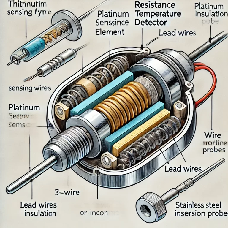
Platinum Resistance Temperature Detectors (RTDs) are widely recognized for their accuracy, stability, and linear temperature-resistance relationship. RTDs utilize platinum as their sensing element, leveraging the material’s predictable changes in resistance in response to temperature variations. The design of an RTD sensor requires careful attention to multiple factors, including the sensing element, insulation, lead design, housing, and installation method. Here, we explore these components in detail.
1. Platinum Sensing Element
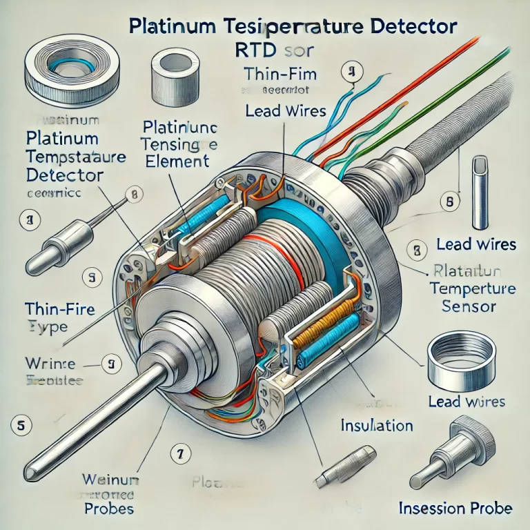
The core of an RTD sensor is the platinum sensing element. Platinum is chosen due to its high stability and linearity over a broad temperature range. Two common types of platinum sensing elements include:
- Pt100: A platinum element with a resistance of 100 ohms at 0°C.
- Pt1000: A platinum element with a resistance of 1000 ohms at 0°C.
Types of Sensing Element Design
There are two main designs for platinum elements: thin-film and wire-wound. Each has its own characteristics, suitable for different applications.
Thin-Film Platinum Element: In this design, a thin layer of platinum is deposited onto a ceramic substrate, and the resistor pattern is etched or laser-cut into the surface. This design allows for compact sensors, fast response times, and improved resistance to vibration. Thin-film elements are often favored for high-volume manufacturing because of their lower cost and rapid production process.
Wire-Wound Platinum Element: In this type, platinum wire is coiled around a ceramic or glass core. Wire-wound RTDs provide superior accuracy, especially at higher temperatures, but they tend to have slower response times due to the larger mass of the element. Wire-wound elements are highly stable and are ideal for precision measurement over extended temperature ranges (-200°C to 850°C).
The design of the platinum element must also account for the temperature coefficient, which is typically 0.00385 Ω/Ω/°C, meaning the resistance increases by 0.385 ohms per degree Celsius rise.
2. Lead Wire Configuration
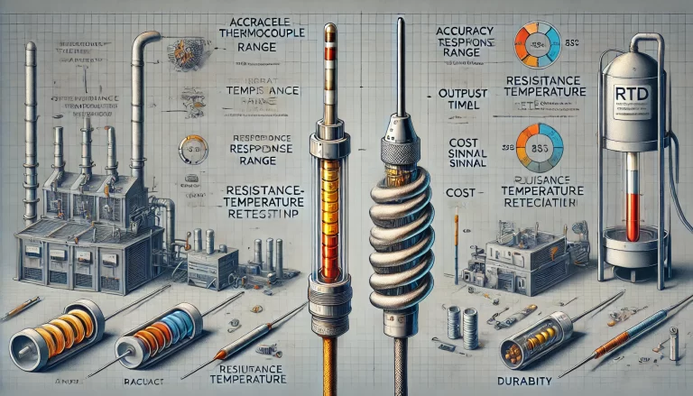
The lead wire configuration plays a crucial role in the overall accuracy of the RTD. Since the sensor works by measuring changes in resistance, any additional resistance from the lead wires can introduce error. To minimize this, different lead wire configurations are used:
2-Wire Configuration: The simplest design where two wires connect the RTD element to the measurement instrument. This configuration is only suitable for short distances and low-precision applications, as it does not account for the resistance of the lead wires.
3-Wire Configuration: A more common design in industrial applications, where a third wire is added to compensate for the resistance of the lead wires. By measuring the resistance of the third wire, the effect of the lead resistance can be partially negated, improving accuracy.
4-Wire Configuration: This is the most accurate design, completely eliminating the effect of lead wire resistance. In this configuration, two wires are used to provide the current, and two separate wires are used to measure the voltage. This configuration is ideal for laboratory and high-precision applications.
Lead Wire Material
The choice of lead wire material is crucial for ensuring long-term stability and minimizing thermal EMF (electromotive force). Common materials include:
- Copper: Offers good conductivity and is suitable for low-temperature applications.
- Nickel: Used in environments with moderate temperatures, providing resistance to corrosion.
- Silver: Chosen for high-temperature applications due to its excellent conductivity and thermal properties.
3. Insulation
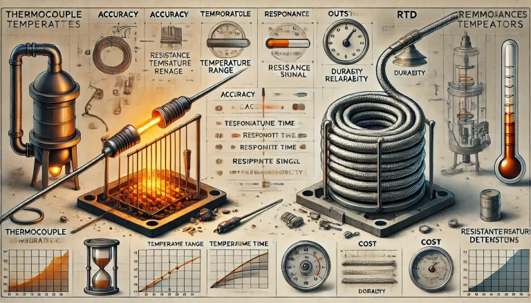
Insulation serves to electrically isolate the platinum element and the lead wires from one another and the environment. It is essential for ensuring the sensor’s longevity and accurate performance. Several types of insulation materials are used, depending on the application:
Ceramic Insulation: Provides excellent high-temperature stability and is typically used in high-precision wire-wound RTDs. Ceramic offers robust mechanical protection and resistance to thermal shocks, making it suitable for extreme environments.
Glass Insulation: Another high-temperature material that is used in high-accuracy sensors. It is especially resistant to moisture and chemical damage.
Polymer or Silicone Insulation: These materials are used in low- to medium-temperature environments, where flexibility and moisture resistance are essential.
4. Housing and Protection
The external housing or sheath provides mechanical protection for the RTD and ensures that it can function in challenging environments, such as corrosive atmospheres or areas exposed to mechanical vibrations. Housing materials must be chosen based on the environment where the sensor will be deployed.
Common Housing Materials:
Stainless Steel: The most common material for RTD housings, offering excellent corrosion resistance, mechanical strength, and temperature tolerance. Stainless steel is suitable for a wide range of industrial environments.
Inconel: A high-performance nickel-chromium alloy used in extreme conditions, such as high-temperature or high-corrosion environments. It provides enhanced durability and is used in more specialized applications.
Protection and Sealing:
To ensure the RTD is protected from moisture, dust, and other contaminants, the housing is typically sealed. The sealing method varies, with epoxy resin often used in lower-temperature applications and hermetic seals (such as glass-to-metal seals) used in high-temperature or high-vacuum environments.
5. Installation and Mounting
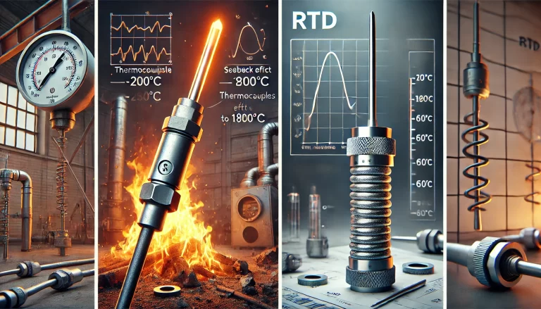
RTDs can be installed in various ways, depending on the application. Common installation types include:
Threaded Probes: Sensors that are mounted using threads, typically in pipelines or machinery where the sensor needs to be securely screwed into place.
Flange Mounts: These are used in applications where the RTD needs to be surface-mounted to a piece of equipment or machinery.
Insertion Probes: Designed to be inserted into a process via a hole or well, these sensors are typically used in liquid or gas environments where direct contact with the medium is needed.
6. Calibration and Accuracy
Accuracy is a critical feature of RTD sensors, and they are often calibrated to meet specific standards such as DIN/IEC 60751, which defines the relationship between temperature and resistance. Calibration allows for precise temperature measurement and correction of any systematic errors.
Tolerance Classes:
RTDs are typically classified according to tolerance classes. The most common are:
Class A: Offers higher accuracy, with a tolerance of ±(0.15°C + 0.002*|t|), where |t| is the absolute temperature.
Class B: Provides good accuracy for general industrial use, with a tolerance of ±(0.3°C + 0.005*|t|).
7. Response Time
The response time of an RTD is an important consideration, particularly in dynamic temperature environments. The response time is influenced by:
Element Design: Thin-film RTDs have faster response times compared to wire-wound types.
Housing and Protection: Larger housings or thicker sheaths can slow down response times as they increase the thermal mass of the sensor.
Immersion Depth: Ensuring proper immersion in the medium being measured can improve response times, as more of the sensor is exposed to the temperature change.

Conclusion
The structural design of platinum RTD sensors is a sophisticated process that requires consideration of material properties, environmental conditions, and accuracy requirements. Each element of the design—from the platinum sensing element to the lead wire configuration, insulation, and housing—plays a crucial role in determining the performance of the sensor. By carefully balancing these design factors, RTD sensors can provide highly accurate and reliable temperature measurements over a wide range of industrial and laboratory applications.
