1. Introduction
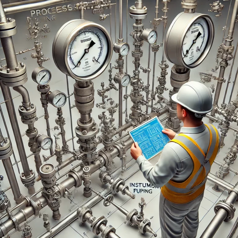
Piping and Instrumentation Diagrams (P&IDs) are crucial components of chemical process design. They serve to clearly illustrate all equipment, instruments, pipelines, valves, and related utilities in the process system. This document outlines the typical design considerations for pressure, temperature, pumps, and vessel-related P&ID diagrams.

2. Design Pressure
2.1 Terminology
Gauge Pressure (G) / Absolute Pressure (A): Denoted with “G” or “A”. Default is gauge pressure if unspecified.
Maximum Operating Pressure: The highest pressure that may occur under normal operation at the top of the vessel.
Shut-off Pressure: Maximum discharge pressure when pump/compressor outlet is blocked.
Set Pressure of Safety Valve: Pressure at which the valve begins to open.
Design Pressure: The maximum pressure a vessel or pipe is designed to withstand, considering all system variables and not less than the maximum operating pressure.
2.2 Codes and Standards
GB150: For pressure between 0.1 MPa(G) and 35 MPa(G), or vacuum >2kPa.
GB/T4735: For pressure <0.1 MPa(G) or vacuum <=2kPa.
Above 35 MPa(G): Use applicable industry codes.
2.3 Pressure Determination Principles
Design pressure is established based on equipment function, fluid properties, pressure surges, and safety requirements. Special attention is given to toxic, flammable, or volatile substances, and to operations like heating, regeneration, or catalyst replacement.

3. Design Temperature
Design temperature refers to the metal temperature of the component under the highest pressure during normal operation. It is determined based on process conditions or calculated from heat transfer data.
3.1 Equipment
If external insulation is present, wall temperature = design temperature.
For direct steam heating, use the maximum medium temperature.
For multi-temperature environments, the higher temperature is used unless it drops below -20°C.
3.2 Piping
Design temperature is based on the wall temperature under normal maximum operating conditions.
For metallic pipes with media >38°C: T = 95% of max media temp.
For cryogenic systems or non-metallic linings, consider environment temperature effects.

4. Pump P&ID Design
4.1 Centrifugal Pump
Key Elements:
Inlet/outlet isolation valves (usually gate valves)
Strainers at inlet
Check valve and pressure gauge at outlet
Drain/vent lines with valves on pump body and piping
Balance line to avoid cavitation if vaporization is possible
Minimum flow line with restriction orifice
Bypass line for high-head pumps
Warm-up or anti-solidification lines if temperature-sensitive media
4.2 Reciprocating Pump
No need for outlet check valve
Safety valve installed between pump outlet and isolation valve
Discharge to suction side or inlet vessel

5. Vessel P&ID Design
5.1 Horizontal Vessels
Vent and drain valves at top and bottom
Utility connections with isolation valves
Level gauges and pressure indicators mounted via standpipes
Safety valve on top or gas line
Support elevation indicated if necessary
5.2 Vertical Vessels with Nitrogen Sealing
Nitrogen supply and condensate drain lines
Steam tracing for vessels and piping
No bypass or upstream isolation if batch operation
5.3 Agitated Vessels
Agitator reduces the need for vortex breaker
Discharge from tank bottom to pump inlet

6. Design Considerations Summary
| Component | Design Pressure | Design Temperature |
|---|---|---|
| Vessel | Max working pressure + safety factors | Highest wall temp or media temp + margin |
| Piping | Equal or higher than connected equipment | Based on most severe condition or heat transfer calc |
| Pump | Shut-off pressure + static head | Media temperature, warm-up lines if needed |
