Boiler drum level transmitters play a critical role in maintaining the safe and efficient operation of a boiler system. These instruments measure the differential pressure across the water and steam sides of the drum to determine the water level. Depending on the installation orientation of the transmitter, forward or reverse, the signal interpretation in the Distributed Control System (DCS) needs to be configured accordingly. Misconfiguration can lead to incorrect level readings, potentially causing unsafe operating conditions.
1. Forward and Reverse Installation Explained
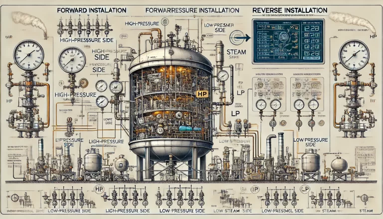
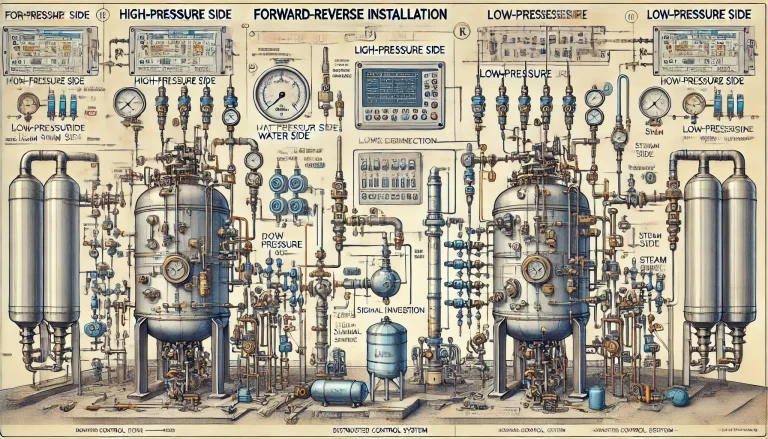
Forward Installation (Normal Orientation)
- High-Pressure Side (HP): Connected to the drum’s water side (lower connection).
- Low-Pressure Side (LP): Connected to the drum’s steam side (upper connection).
In this configuration:
- When the water level increases, the pressure on the HP side increases relative to the LP side.
- The differential pressure rises, and the transmitter output increases proportionally.
Reverse Installation (Inverted Orientation)
- High-Pressure Side (HP): Connected to the drum’s steam side (upper connection).
- Low-Pressure Side (LP): Connected to the drum’s water side (lower connection).
In this configuration:
- When the water level increases, the pressure on the HP side decreases relative to the LP side.
- The differential pressure decreases, and the transmitter output decreases proportionally.

2. Differential Pressure Transmitter Basics
A differential pressure transmitter typically outputs a signal in the range of 4–20 mA or 0–10 V, corresponding to the measured water level. The output signal must accurately reflect the actual water level in the drum, regardless of whether the transmitter is installed forward or reverse.
- 4 mA Output: Typically represents the lowest measurable water level (e.g., 0% level).
- 20 mA Output: Typically represents the highest measurable water level (e.g., 100% level).
3. Configuring the DCS for Forward Installation
In forward installation, the transmitter output signal directly corresponds to the water level:
- High water level = High differential pressure = High signal output.
- The signal increases linearly from 4 mA to 20 mA as the water level rises.
DCS configuration steps:
- Set the input range to match the transmitter output, typically 4–20 mA.
- Define the range of the level measurement in engineering units (e.g., 0 mm to 500 mm water column).
- Calibrate the transmitter to ensure the signal corresponds to actual water levels.
4. Configuring the DCS for Reverse Installation
In reverse installation, the transmitter’s output signal is inverted relative to the water level:
- High water level = Low differential pressure = Low signal output.
To account for this, the DCS must be configured to interpret the signal in reverse:
- Enable Signal Inversion:
- Use the DCS’s software settings to reverse the input signal mapping.
- For example, configure 4 mA to represent 100% water level and 20 mA to represent 0% water level.
- Set Scaling Parameters:
- Adjust the input range to match the reversed signal.
- Define the level range as before, ensuring the DCS interprets 4 mA as the highest level and 20 mA as the lowest level.
- Calibrate the System:
- Perform a calibration process to validate that the level readings are correct.
- Use simulation or manual input to test the DCS response to various levels.
5. Key Considerations for Both Installations
A. Zero and Span Calibration
- Ensure the transmitter is zeroed correctly at the lowest level and spanned at the highest level.
- This step ensures the transmitter’s output range matches the physical water level range.
B. Verify Signal Linearity
- Check that the transmitter’s signal increases or decreases linearly with the water level.
- Conduct tests using known reference levels.
C. Account for Static Pressure
- Boiler systems operate under high pressure, which affects the density of water and steam. The transmitter’s configuration should account for this static pressure to ensure accurate measurements.
D. Prevent Signal Disturbances
- Ensure the impulse lines connecting the transmitter to the drum are free from blockages (e.g., no water or steam traps in the lines).
- Regularly inspect and maintain the transmitter to prevent measurement errors.
6. Testing and Validation
After configuring the DCS:
Simulate Different Water Levels:
- Use a pressure generator or physical level simulator to mimic changes in water level.
- Verify the DCS readings match expected values for both forward and reverse installations.
Monitor System Operation:
- Observe the boiler’s water level trends during actual operation.
- Ensure the configured alarms for high and low levels are triggered correctly.
Conduct Safety Checks:
- Test the safety interlocks associated with water level control to prevent dry firing or water carryover into the steam lines.

7. Troubleshooting Common Issues
A. Incorrect Signal Mapping
- Symptom: The DCS displays the opposite water level trend (e.g., high level when the drum is nearly empty).
- Solution: Verify whether the transmitter is installed forward or reverse and reconfigure the DCS input scaling accordingly.
B. Fluctuating Signals
- Symptom: The level reading fluctuates significantly.
- Solution: Check for air or water pockets in the impulse lines and ensure proper line purging.
C. Inconsistent Calibration
- Symptom: Level readings do not match physical measurements.
- Solution: Recalibrate the transmitter and validate the DCS configuration.
8. Conclusion
Whether installed forward or reverse, the accurate configuration of a boiler drum level transmitter with the DCS is crucial for safe and efficient operation. By understanding the principles of differential pressure measurement and carefully configuring the DCS to interpret signals correctly, operators can ensure reliable water level monitoring. Regular testing, calibration, and maintenance further enhance system reliability and safety.
