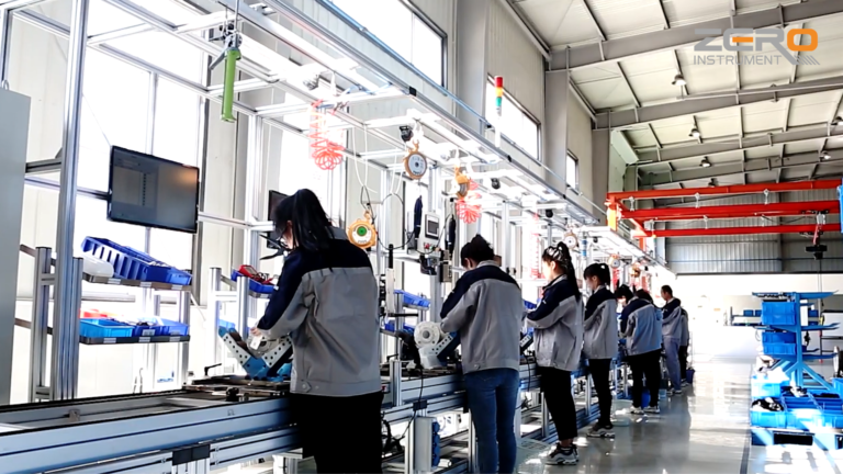
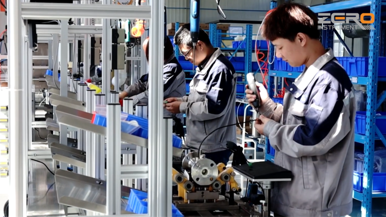
In industrial settings, it is often necessary to measure various non-electrical physical quantities, such as pressure, liquid level, temperature, differential pressure, humidity, soil moisture, and more.
To transmit these physical quantities to a control room or display device, which could be hundreds of meters away, they need to be converted into standard analog electrical signals. Devices that perform this conversion are known as transmitters.
The most widely used standard analog signal in industry is the 4-20 mA two-wire DC current system, which transmits these analog values reliably.
To implement a two-wire system in a transmitter, the following conditions must be satisfied:
Voltage Condition: The output voltage of the transmitter, denoted as v, must be less than or equal to the minimum specified power supply voltage minus the voltage drop caused by the current flowing through the load resistor and the resistance of the transmission wires. Mathematically, this is expressed as: v≤emin−imax⋅rLmaxv \leq e_{min} – i_{max} \cdot r_{L_{max}}v≤emin−imax⋅rLmax Where:
v is the output voltage.
e_{min} is the minimum power supply voltage.
i_{max} is the maximum current (20 mA for most systems).
r_{L_{max}} is the sum of the load resistance and transmission line resistance.
Current Condition: The operating current of the transmitter, i, must be less than or equal to the output current of the transmitter. This ensures that the transmitter operates within its designed current range: i≤imini \leq i_{min}i≤imin Where:
i_{min} is the minimum current, typically 4 mA in a 4-20 mA system.
Power Condition: The minimum power consumption p of the transmitter must not exceed a specific value. It is constrained by the minimum operating current and voltage drop across the load resistor: p<imin⋅(emin−imin⋅rLmax)p < i_{min} \cdot (e_{min} – i_{min} \cdot r_{L_{max}})p<imin⋅(emin−imin⋅rLmax) Generally, the minimum power consumption should be less than 90 mW.
The parameters used are:
e_{min} = minimum power supply voltage. For most instruments, e_{min} is 24 V with a tolerance of ±5%, meaning the actual minimum is 22.8 V.
i_{max} = 20 mA.
i_{min} = 4 mA.
r_{L_{max}} = the maximum load resistance, typically 250 ohms, plus the resistance of the transmission lines.
As long as the transmitter is designed to meet these three conditions, it can implement a two-wire transmission system. In industrial applications, the measurement points are usually located on-site, while the display or control devices are typically in a control room or cabinet, often tens to hundreds of meters away.
For a distance of 100 meters, eliminating two signal transmission wires could reduce costs by nearly 100 yuan. Additionally, the 4-20 mA two-wire signal output is less susceptible to interference, making it a safer and more reliable option.