Abstract
Instrumentation and control systems are essential for stable, safe, and efficient industrial operations. However, failures inevitably occur due to various technical, environmental, and human factors. This document provides a comprehensive framework for fault diagnosis, organized into five systematic approaches:
Causes of failures in instruments and control systems.
Common fault factors in field instruments.
Fault analysis using control loop concepts.
Practical strategies for troubleshooting.
The “One-Two-Three” principle of instrument maintenance.
Diagrams, flowcharts, and tabular summaries are recommended to enhance clarity and usability for engineers and maintenance personnel.
1. Causes of Instrument and Control System Failures
1.1 Failure Modes
Early failure: Hidden defects in design/manufacturing.
Normal failure: Wear and aging of components after service life.
1.2 Common Causes
Poor electrical contact – oxidation, loose connectors, defective PCB vias.
Corrosion, leakage, and clogging – due to harsh media and environment.
Welding defects – cold solder joints, cracked welds, stress fatigue.
Mechanical wear – bearings, gears, actuator components.
Overheating – excessive current, poor heat dissipation, degraded insulation.
Power supply anomalies – undervoltage, overvoltage, surges, lightning.
Human error – miswiring, incorrect polarity, mishandling, improper adjustments.
Interference – electromagnetic or frequency converter noise.
Table 1 — Typical Fault Causes vs. Observable Symptoms
| Fault Cause | Observable Symptoms | Notes / Typical Scenarios |
|---|---|---|
| Component Failure | No display, output stuck at maximum/minimum, valve fails to move | Early failure (manufacturing defects) or end-of-life failure |
| Poor Electrical Contact | Intermittent signal, unstable readings, heating at terminals, sudden signal loss | Oxidized connectors, loose plugs, poor PCB via connections |
| Corrosion / Leakage | Signal drift, erratic measurement, zero-point offset, process medium leakage | Impulse lines, flanges, valves exposed to corrosive media |
| Welding Defects | Gradual increase in resistance, intermittent circuit break, loss of mechanical sealing | Cold solder joints, cracked welds, stress-induced fatigue |
| Mechanical Wear | Valve stem stuck, actuator sluggish, recorder pen fails, noise during operation | Bearings, gears, lubricants drying out, plastic parts cracking |
| Overheating | Sudden failure of capacitors, insulation breakdown, burnt smell, continuous drift | Overcurrent, poor cooling, high ambient temperature |
| Power Supply Issues | Instrument resets, permanent damage to power board, multiple devices fail simultaneously | Overvoltage, undervoltage, lightning surge, unstable grid |
| Human Error | Reverse polarity, wrong wiring, calibration lost, instrument physically damaged | Misoperation, improper installation, accidental drop |
| Electromagnetic Interference (EMI) | Display fluctuation, random alarms, communication errors | Near VFDs, motors, high-frequency devices |
2. Fault Factors in Field Instruments
Despite high reliability of modern DCS and panel-mounted instruments, field devices still face high failure rates.
2.1 Environmental Factors
Poor sealing – ingress of water, dust, corrosive gases.
Corrosion – affecting housings, fasteners, impulse lines, valves.
Vibration – loosening of bolts, fittings, cracks in welds.
Process and equipment effects – e.g., furnace bricks damaging thermowells, pump vibrations dislodging gauge needles, electromagnetic interference.
2.2 Human Factors
Incorrect instrument selection/installation.
Improper maintenance or inspection.
Damage during equipment overhauls or cable theft.
2.3 Instrument Quality Issues
Batch or model-related defects leading to recurring failures.
Table 2 — Field Instrument Failure Causes and Preventive Measures
| Cause Category | Specific Issues | Preventive Measures |
|---|---|---|
| Environmental Factors | – Poor sealing → water, dust, or gas ingress – Corrosion of housing, bolts, impulse lines, valves – Vibration loosening bolts, fittings, terminals – Process impact (e.g., furnace brick collapse damaging thermowell, pump vibration dislodging gauge needle) – Electromagnetic interference from nearby equipment | – Ensure cable entry sealing, use silicone/epoxy for weak points – Select corrosion-resistant materials, apply protective coatings, add isolation – Use spring washers, regular torque checks, anti-vibration pads/support frames – Add protective shields, vibration dampers, or better instrument placement – Improve grounding/shielding, increase EMC immunity |
| Human Factors | – Improper instrument selection – Incorrect installation or orientation – Inadequate maintenance – Damage during overhaul (bent thermowells, broken gauges, cut cables) – Theft of instrument parts or cables | – Conduct proper engineering design and selection review – Follow standard installation guidelines (e.g., straight-run requirements, mounting height) – Implement preventive maintenance and inspection schedule – Supervise overhaul operations, protect installed instruments – Secure instruments/cables with protective covers and anti-theft measures |
| Instrument Quality Issues | – Random failures due to manufacturing defects – Recurrent failures from specific batch/model | – Perform vendor qualification and incoming inspection – Replace faulty models with reliable alternatives – Establish failure tracking database to identify systemic issues |
3. Fault Analysis Using Control Loop Concepts
Breaking down systems into individual loops helps simplify complex fault tracing.
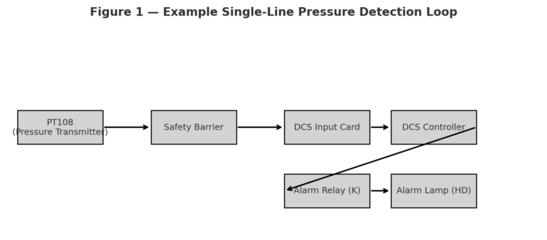
3.1 Instrument Loop Diagrams
Single-line loop diagram (e.g., pressure detection & alarm).
Double-line loop diagram (e.g., compressor anti-surge control).
3.2 Loop Decomposition Examples
Temperature control loop – RTD → transmitter → controller → actuator.
Level control & interlock loop – transmitter → DCS → I/P converter → valve.
Cascade control configuration – master and slave PID regulators.
Differential pressure flow loop – impulse lines, valves, transmitter.
4. Practical Troubleshooting Strategies
Understand system principles: know the function of each unit and signal relationship.
Surface-to-core analysis: start from observable phenomena, infer causes.
Examples:
Thermocouples – hot junction generates EMF proportional to temperature.
Electromagnetic flowmeters – induced voltage proportional to flow rate.
Level controllers – current signal proportional to deviation, valve response.
5. The “One-Two-Three” Principle of Instrument Maintenance
5.1 One: Loop-by-Loop Checking
Check supply loop, measurement loop, and control loop separately.
5.2 Two: Split-Point Diagnosis (Divide & Conquer)
Use midpoint or 0.618 golden ratio method to split the system for efficient fault localization.
5.3 Three: Three-Step Repair
Identify the fault location (sensor, transmitter, controller, valve, or DCS).
Repair the identified fault.
Recommission and observe to confirm resolution.

Table 3 — Three-Step Fault Handling Checklist
| Step | Key Actions | Purpose / Expected Outcome |
|---|---|---|
| 1. Fault Identification | – Verify sensor/transmitter input signals (e.g., 4–20 mA, resistance, switch status) – Check controller/DCS outputs to actuators (valves, I/P converters, relays) – Narrow down fault location: sensor, transmitter, controller, actuator, or DCS | Pinpoint the faulty component or subsystem, avoiding unnecessary replacements |
| 2. Fault Treatment | – Repair or replace defective components (sensor, transmitter, controller module) – For valve/DCS issues: conduct targeted repair (mechanical service, recalibration, or software reset) – Ensure wiring, polarity, and configuration are correct | Resolve the root cause, restore instrument/system functionality |
| 3. Recommissioning & Observation | – Reconnect and return system to service – Observe performance under actual operating conditions – Monitor intermittent faults over time (since some are sporadic) | Confirm system stability, ensure fault does not reappear, validate repair effectiveness |
Conclusion
Effective fault diagnosis in instrumentation requires:
Comprehensive understanding of failure modes and environmental influences.
Application of loop-based analysis for systematic troubleshooting.
Use of structured methods such as the “One-Two-Three” principle for efficient repair.
By combining theoretical knowledge with practical strategies and clear diagrams, maintenance personnel can ensure higher reliability, reduced downtime, and safer industrial operations.