Differential pressure (DP) flow meters operate on the throttling principle, derived from the Bernoulli equation. They calculate flow rate by measuring the static pressure difference generated as the fluid passes through a restriction (such as an orifice plate or venturi tube), and combining it with known physical parameters.
1.1 Working Principle
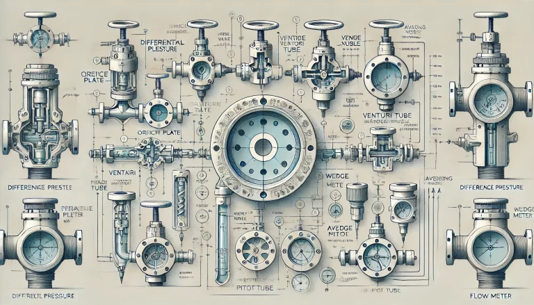
When a fluid flows through a throttling device (e.g., orifice plate, nozzle, venturi tube), the flow accelerates and pressure drops at the constriction, generating a pressure difference (ΔP) proportional to the square of the flow rate.
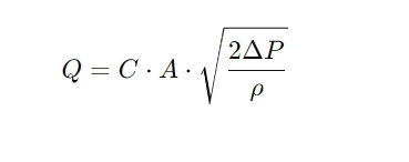
1.2 Core Equation
Where:
Q: Volumetric flow rate
C: Flow coefficient (dependent on the device geometry and Reynolds number)
A: Throat cross-sectional area
ρ: Fluid density
ΔP: Differential pressure
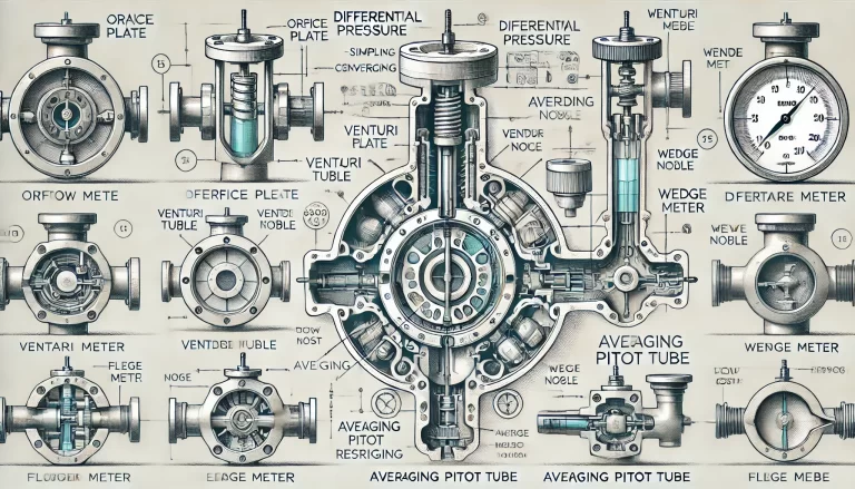
2. Types of DP Flow Meters and Throttling Devices
Type
Structure & Characteristics
Advantages
Limitations
Applications
Orifice Plate
Simple concentric bore
Standardized, low cost, wide usage
High pressure loss, lower accuracy
Clean gases/liquids
Flow Nozzle
Curved inlet, cylindrical outlet
Higher accuracy, wear-resistant
Costlier, more complex
High-speed/high Re number fluids
Venturi Tube
Converging-throat-diverging profile
Minimal pressure loss, high accuracy
Bulky, expensive, space-intensive
Water utilities, low energy loss
Wedge Meter
Sharp V-shaped wedge
Strong anti-clogging, for viscous fluids
Requires calibration, custom design
Slurry, particle-laden fluids
Averaging Pitot (Annubar)
Multiple pressure ports
Low pressure loss, easy to install
Lower accuracy, sensitive to flow profile
Steam, clean gas, large pipes
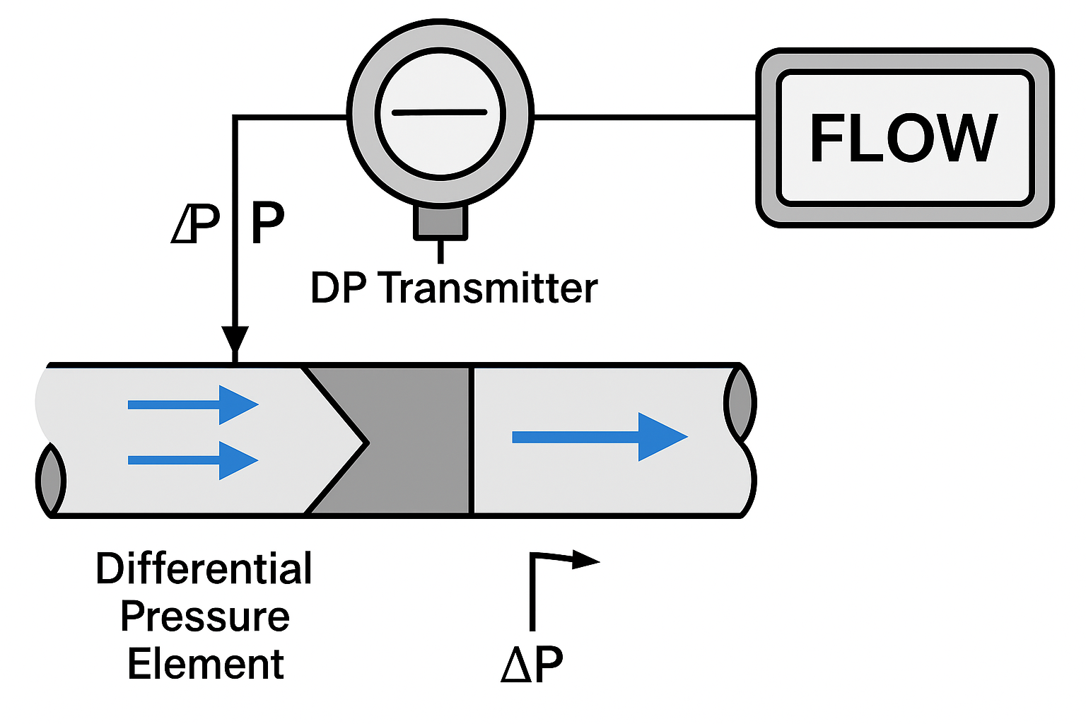
3. System Components
A DP flow meter system typically includes:
Primary Element (Restriction Device): Generates ΔP.
Differential Pressure Transmitter: Converts ΔP, temperature, and pressure into standardized signals (e.g., 4–20 mA, HART, Modbus), with density compensation for gases/steam.
Display and Calculation Unit: Computes instantaneous and totalized flow; supports local display, remote communication, or integration into DCS.
4. Technical Characteristics
Advantages
High Versatility: Suitable for gases, liquids, steam under extreme conditions (–200°C to +850°C, 0–40 MPa).
Standardized Design: Complies with ISO 5167, GB/T 2624; standard designs do not require calibration.
Proven Technology: Widely accepted and field-proven.
Limitations
Pressure Loss: Notably high for orifice plates, increasing energy cost.
Limited Turn-down Ratio: Typically 3:1 to 5:1; proper sizing is crucial.
Installation Sensitivity: Requires long upstream/downstream straight pipe runs.
Media Sensitivity: Clogging risk with dirty fluids; requires density, viscosity compensation.
Consider required straight runs and maintenance access.
9. Comparison with Other Flow Meters
Type
Advantages
Disadvantages
Typical Applications
DP Flow Meter
Widely applicable, standardized
High pressure loss, narrow turn-down
Multiphase and harsh fluids
Vortex Flow Meter
No moving parts, wide range
Sensitive to vibration, low Re accuracy
Clean liquids/gases (e.g., air, water)
Electromagnetic Meter
No pressure loss, for conductive liquids
Not suitable for non-conductive media
Wastewater, corrosive fluids
Ultrasonic Flow Meter
Non-invasive, ideal for large pipes
Accuracy affected by pipe condition
Water metering, large pipelines
10. Development Trends
Smart Capabilities: Integrated temperature/pressure compensation, online diagnostics, wear detection, advanced signal processing for turn-down ratio >10:1.
Low Power & Wireless: Battery + wireless modules for remote locations (e.g., natural gas pipelines).
Custom Throttling Designs: Twin-wedge, hybrid elements for complex fluids.
Digital Verification: CFD simulation for optimized design and reduced calibration cost.
Conclusion
Differential pressure flow meters remain a cornerstone of industrial flow measurement due to their versatility, standardization, and reliability. Despite challenges such as pressure loss and installation constraints, they are ideal for multipurpose flow measurement across industries. With smart features and digital enhancements, their role will continue to evolve toward higher efficiency and intelligence.