Instrument wiring and commissioning is critical in industrial automation, laboratories, or engineering applications. This document provides detailed guidelines and best practices to ensure accuracy, reliability, and safety in wiring and commissioning temperature, pressure, flow, and level instruments.
1. Instrument Wiring Essentials
Temperature Instruments
Thermocouples:
Clearly distinguish polarity (typically red for positive).
Ensure compensation cables match thermocouple materials.
Route cables away from power lines to prevent electromagnetic interference (EMI).
Resistance Temperature Detectors (RTDs, e.g., PT100):
Use 3-wire or 4-wire configurations to reduce measurement error from wire resistance.
Ensure consistent wire lengths and resistance for accurate readings.
Secure all terminals firmly to avoid intermittent contact.
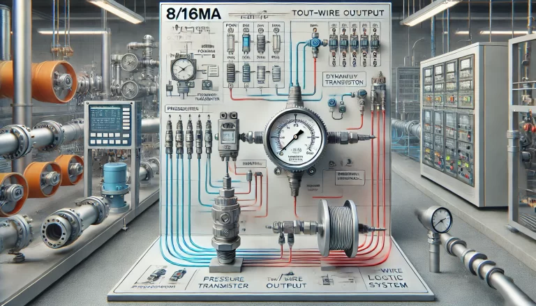
Pressure Transmitters
Two-wire transmitters:
Connect in series with a 24V DC power source; positive to power, negative to signal input.
Confirm loop resistance stays within allowed limits (usually ≤250Ω).
Four-wire transmitters:
Separate power (220V AC or 24V DC) from signal wires.
Shield and ground signal cables to minimize interference.
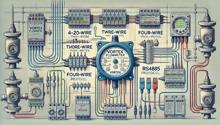
Flow Meters
Electromagnetic Flow Meters:
Utilize dedicated shielded cables between sensors and converters.
Ensure pipes are fully filled and properly grounded.
Vortex/Turbine Flow Meters:
Connect pulse outputs to frequency input modules, observing correct signal type (NPN/PNP).
Install anti-vibration supports to reduce measurement errors.
Level Instruments
Radar/Ultrasonic Level Meters:
Shield cables carefully and avoid proximity to high-power devices (e.g., motors, frequency converters).
Install sensors clear of physical obstructions (pipes, agitators).
Float Level Switches:
Connect dry contacts to appropriate relays or PLC inputs, matching relay contact ratings.
General Wiring Principles
Shielding and Grounding: Use shielded cables, grounding only one end (usually at the control cabinet). Maintain grounding resistance ≤4Ω to avoid ground loops.
Short-Circuit/Disconnection Prevention: Verify instrument voltage ratings (24V or 220V) before wiring. Use crimp terminals or solder connections to prevent loose contacts.
2. Instrument Commissioning Procedure
Pre-commissioning Checks
Safety Confirmation: Perform wiring with power disconnected. Inspect thoroughly for shorts or exposed wires. In explosive areas, confirm instrument compliance with explosion-proof standards.
Parameter Verification: Confirm instrument range, units, and output signal type (4-20mA, 0-10V, Modbus) match system specifications.
Commissioning Steps
Power-up Tests: Monitor voltage/current upon initial energization. Use a multimeter to confirm output signals are within expected ranges.
Zero and Span Calibration:
Zero Calibration: Set outputs accurately at no-input condition (e.g., atmospheric pressure for transmitters at 4mA or 0%).
Span Calibration: Provide full-scale input (maximum pressure or temperature) and set output precisely at 20mA or 100%. Smart instruments can utilize HART protocol or handheld configurators for automated calibration.
Dynamic Testing: Simulate real operating conditions (e.g., gradual temperature or pressure increase) and observe system response for linearity and stability. Verify proper activation of alarms and interlocks.
3. Troubleshooting Common Issues
No Output Signal: Verify proper power supply and continuity. Check for protective statuses like sensor faults or over-range conditions.
Significant Measurement Errors: Recalibrate zero and span. Inspect sensors for physical damage or deterioration.
Signal Instability: Inspect connections for looseness. Isolate sensitive instrument cables from strong EMI sources (e.g., frequency converters, motors).
4. Documentation and Safety Precautions
Maintain Documentation: Preserve calibration records, wiring diagrams, and settings for future maintenance.
Safety Compliance: Use intrinsically safe instruments in explosive environments. Wear proper protective gear when dealing with high-voltage or high-temperature scenarios.
By adhering strictly to these comprehensive guidelines, engineers and technicians can significantly enhance measurement accuracy and system reliability, ensuring safer and more efficient operational outcomes.