Installing instrument cable trays properly and in compliance with relevant standards is crucial to ensure safety, functionality, and durability. Below is a detailed guide on how to design and install cable trays that meet regulatory standards.
1. Adherence to Standards and Regulations
Cable tray installations must comply with applicable local and international standards, such as:
- GB 50303: Code for Installation and Acceptance of Electrical Equipment
- CECS 31: Code for Design of Cable Tray Engineering
- IEC 61537: International Standard for Cable Management
These standards provide guidelines on material selection, tray placement, load capacity, and safety requirements.

2. Route Selection for Cable Trays
Proper route selection ensures minimal interference, ease of maintenance, and system reliability. Key considerations include:
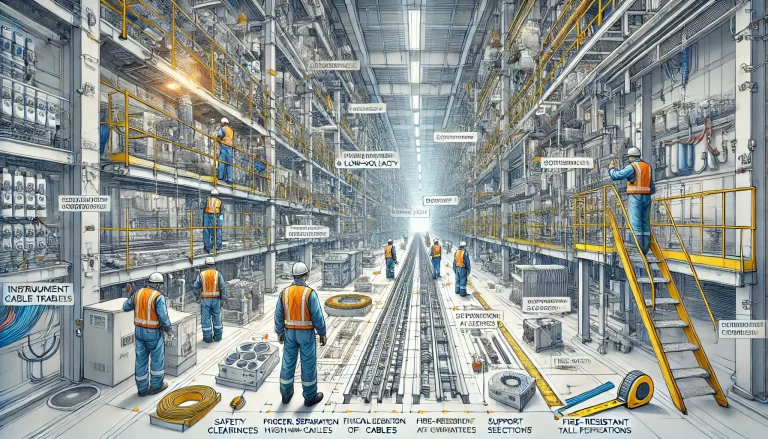
- Avoid Electromagnetic Interference (EMI): Install the tray away from high-voltage power cables, transformers, motors, and other sources of electromagnetic interference.
- Straight Routes: Minimize unnecessary bends and elevation changes. If unavoidable, use appropriate fittings such as bends, elbows, and reducers to maintain tray integrity.
- Access for Maintenance: Place cable trays where there is sufficient clearance for future inspection and maintenance activities.
3. Separation of Different Cable Types
Different types of cables should be arranged to minimize interference and ensure safety. Follow these guidelines:
- Layered or Segmented Layout: Arrange power cables, control cables, and signal cables separately within the tray system to reduce cross-talk and signal distortion.
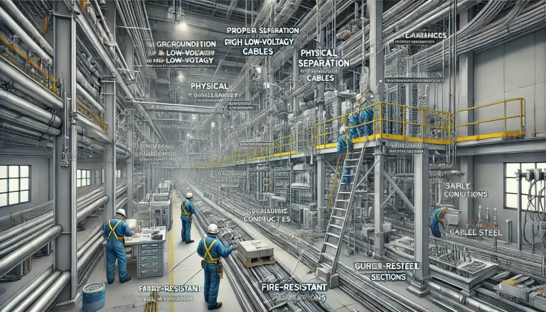
- Physical Separation: Use internal dividers within the cable tray to provide physical separation between high-voltage and low-voltage cables.
4. Wall and Floor Penetrations
When a cable tray passes through walls, floors, or ceilings, special precautions are needed:
- Fire-Resistant Sleeves: Use fire-rated sleeves or conduit to protect the cables where they penetrate walls or floors.
- Fire Sealing: Seal gaps around the penetration points with certified fireproof materials to prevent the spread of smoke and fire between compartments.
5. Tray Support and Installation
Proper support structures are necessary to maintain the integrity of the cable tray system over time.
- Support Spacing:
- Horizontal installations typically require support at intervals of 1.5 to 3 meters.
- Vertical installations require support at intervals of no more than 2 meters.
- Secure Fixing: Ensure that all tray sections and supports are firmly anchored to prevent vibration, sagging, or displacement.
- Expansion Joints: Install expansion joints in long runs to accommodate thermal expansion and contraction.
6. Grounding and Earthing
Cable trays made of conductive materials must be grounded to ensure safety and prevent electrical hazards.
- Equipotential Bonding: Connect the tray system to the facility’s main grounding system to maintain electrical continuity.
- Grounding Conductors: Install grounding conductors where required to protect against electrical faults and induced voltages.
7. Load Capacity and Structural Integrity
The cable tray must be able to support the weight of the installed cables without bending or deformation.
- Load Rating: Follow the manufacturer’s guidelines on the maximum load rating for each section of the tray.
- Overloading Prevention: Ensure that additional future cables do not exceed the designed load capacity. Factor in both static and dynamic loads in your calculations.
8. Cable and Tray Identification
Proper labeling and documentation are essential for efficient system management and troubleshooting.
- Cable Markers: Use durable markers to label each cable according to its purpose, source, and destination.
- Tray Labeling: Label sections of the tray system to indicate cable types, voltage levels, and fire ratings.
9. Environmental Considerations
The installation must take into account the environmental conditions to protect cables and tray structures from damage.
- Moisture and Corrosion Protection: In humid or corrosive environments, use corrosion-resistant materials such as stainless steel, aluminum, or galvanized steel. Apply protective coatings as necessary.
- Temperature Resistance: In high-temperature areas, select cable trays and cables that can withstand the heat without degradation.
10. Maintenance Access and Safety
Cable trays should be installed with maintenance and safety in mind.
- Clearance: Maintain adequate clearance from ceilings, walls, and other obstructions for access during maintenance.
- Safety Barriers: In areas with high pedestrian or vehicle traffic, install safety barriers to protect the cable trays from physical damage.
11. Inspections and Testing
After installation, conduct inspections and tests to verify compliance with design specifications and safety standards.
- Visual Inspection: Check for physical damage, proper alignment, and secure fittings.
- Continuity and Grounding Tests: Ensure that all grounding connections are intact and meet electrical continuity requirements.
- Load Testing: Confirm that the tray can support the designed load without excessive deflection or structural failure.
By following these detailed guidelines, you can ensure that your instrument cable tray installation is compliant, safe, and reliable for long-term operation. Regular inspections and adherence to industry standards will help maintain the integrity and functionality of the system over time.