1. Functional Positioning
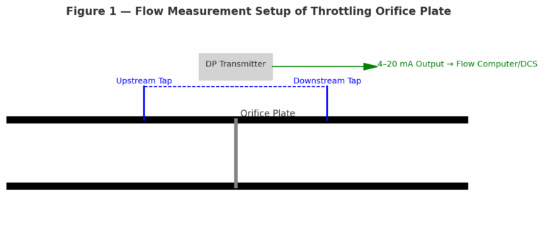
Throttling Orifice Plate: Core component of differential-pressure flow measurement systems. Works with differential pressure transmitters and pressure taps. Its primary function is to generate a pressure drop across the orifice, establishing a quantitative flow–pressure relationship (ISO 5167 standard). Suitable for accurate measurement of single-phase fluids (liquid, gas, steam).
Restriction Orifice Plate: Flow/pressure control device, not intended for precise measurement. Used to limit flow or reduce pressure in pipelines. Typical applications include pump bypass lines, sampling systems, blowdown and venting noise reduction, and erosion protection upstream/downstream of valves.
2. Working Principle
Throttling Orifice Plate: Fluid velocity increases and static pressure decreases at the vena contracta, creating a differential pressure. This pressure signal is transmitted to a DP transmitter and converted into a standard signal (e.g., 4–20 mA), then integrated into a flow computer for instantaneous/totalized flow. Requires strict installation standards (pipe diameter ratio β = d/D, straight pipe length).
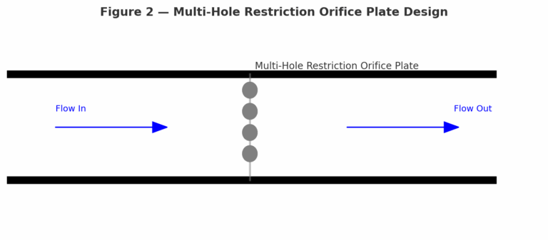
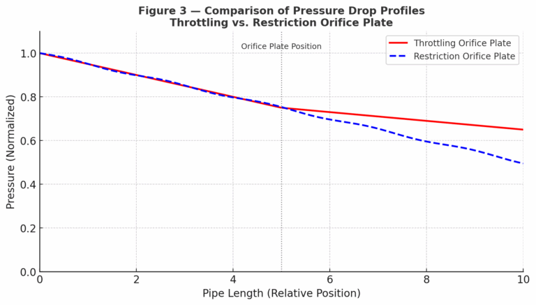
Restriction Orifice Plate: Relies on local resistance to directly limit flow or reduce pressure, without precise DP–flow correlation. To avoid cavitation, the throat pressure must remain above vapor pressure. High-pressure-drop scenarios often adopt multi-stage or multi-hole designs.
3. Application Scenarios
Throttling Orifice Plate:
Process flow monitoring
Energy metering
Laboratory and research use
Must comply with ISO 5167 / GB 2624 standards
Restriction Orifice Plate:
Valve protection under large differential pressures
Blowdown/vent systems for pressure reduction and noise attenuation
Pump bypass or flushing lines requiring continuous low flow
Rough process pressure drop where accuracy is not critical
4. Structure and Design
Throttling Orifice Plate: Standardized structure, high accuracy (±0.5% ~ ±5%), requires calibration. Common pressure tapping methods: corner taps, flange taps, or chamber taps.
Restriction Orifice Plate: Flexible design (single-hole, multi-hole, multi-stage), lower accuracy requirements (within ±10%). Must ensure downstream pressure ≥55% of upstream pressure to avoid choking flow.
Comparison Table: Throttling Orifice Plate vs. Restriction Orifice Plate
| Aspect | Throttling Orifice Plate | Restriction Orifice Plate |
|---|---|---|
| Function | Flow measurement (differential pressure principle) | Flow/pressure control (limit flow or reduce pressure) |
| Measurement Accuracy | High (±0.5% ~ ±5%), requires calibration | Low (typically within ±10%), accuracy not critical |
| Working Principle | Generates differential pressure → transmitted to DP transmitter → flow calculation | Uses flow resistance to reduce pressure or flow, without precise DP–flow correlation |
| Standards | ISO 5167, GB 2624 (mandatory calibration and installation requirements) | HG/T 20570, GD2000 (industry design guidelines, focus on reliability and safety) |
| Design Features | Standardized structure, single orifice, pressure tapping required (corner, flange, chamber) | Flexible design (single-hole/multi-hole, single-stage/multi-stage) |
| Typical Applications | Energy metering, process monitoring, laboratory tests | Valve protection, pump bypass, blowdown systems, noise reduction, small flow pipelines |
| Cavitation Consideration | Must avoid cavitation at throat section; may require multi-stage or anti-cavitation materials | Must ensure downstream pressure ≥55% of upstream; multi-hole or multi-stage used often |
| Focus | Precision, compliance, and accurate measurement | Practicality, reliability, and cost-effectiveness |
5. Standards and Norms
Throttling Orifice Plate: ISO 5167, GB 2624 – requires calibration to ensure accuracy.
Restriction Orifice Plate: Designed per industry standards (e.g., HG/T 20570, GD2000). Cavitation and pressure recovery must be considered, but temperature and Reynolds number effects may be neglected.
6. Special Considerations
Throttling Orifice Plate: Risk of cavitation and material erosion under high ΔP. Multi-stage or anti-cavitation materials may be required.
Restriction Orifice Plate: Focus on reliability and cost-effectiveness. Often employs staged pressure drop or multi-hole design to distribute pressure losses.
Conclusion
Although both devices are based on the same orifice throttling principle, their functional objectives differ significantly:
The throttling orifice plate is a measurement device, focused on accuracy, calibration, and compliance with international standards.
The restriction orifice plate is a control device, focused on limiting flow or reducing pressure, emphasizing practicality and economy.
Correct selection depends on project needs: measurement accuracy vs. control function.