Introduction
Shut-off valves serve as the final control element in Safety Instrumented Systems (SIS), playing a vital role in ensuring process safety. Due to their direct role in executing safety actions, shut-off valves are also among the most failure-prone components within the SIS safety loop.
Depending on their structure and actuation mechanism, shut-off valves respond differently to air supply loss or emergency interlocks. Understanding these configurations and their corresponding failure modes is essential for proper selection, design, maintenance, and SIL verification.
1. Shut-Off Valve Failure Positions (Fail Modes)
Shut-off valves can be categorized according to their behavior upon instrument air loss:
| Mode | Behavior on Air Supply Loss |
|---|---|
| FC | Valve closes (Fail Closed) |
| FO | Valve opens (Fail Open) |
| E | Valve stays at last position (Fail Last) |
| FLC | Valve holds but tends to close (then fully closes when air is depleted) |
| FLO | Valve holds but tends to open (then fully opens when air is depleted) |
These modes are fundamental to interlock design and must align with both process safety and availability requirements.

2. Common Shut-Off Valve Actuator Structures
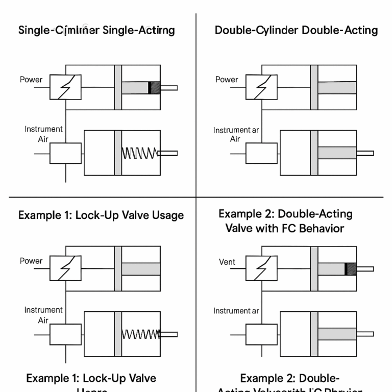
2.1 Single-Cylinder Single-Acting
This is the simplest and most commonly used structure. It includes:
One pneumatic chamber on one end.
A spring on the other end.
Working principle:
Under normal conditions, the solenoid valve is energized, and air pressure compresses the spring to move the valve (open or close).
When power or air is lost (e.g., SIS activation), the air is vented, and the spring returns the valve to its fail position (usually closed).
Failure Mode: Determined by the spring direction. Typically FC or FO.
2.2 Double-Cylinder Double-Acting
Both ends of the actuator are pneumatic cylinders. The valve position is controlled by alternating air supply and exhaust between the two sides.
Working principle:
Air pressure moves the piston in either direction.
In the event of air supply failure, the valve remains in its last position (Fail Last), unless additional mechanisms (e.g., air reservoirs or lock-up valves) are integrated.
Failure Mode: Default is Fail Last (E), but with external logic it can be FC/FO.
2.3 Double-Cylinder Single-Acting
A hybrid solution:
Two cylinders, one of which includes a spring.
Combines the redundancy of dual cylinders with the safety of a spring return.
Working principle:
During normal operation, air pressure and the spring jointly move the valve.
Upon air failure, the spring acts to return the valve to a safe position (usually closed).
Drawback: It is difficult to verify spring performance during routine testing. If the spring weakens over time, emergency shut-off may fail.
3. Influence of Pneumatic Accessories on Failure Modes
In practice, actuator behavior is not determined by structure alone. External pneumatic accessories—such as solenoid valves, air booster relays, lock-up valves, and positioners—play a decisive role.
Example 1: Lock-Up Valve Use
Even a single-acting cylinder may not fail closed if:
The valve is fitted with a lock-up valve.
The lock-up valve holds the actuator pressure when supply drops below a threshold, keeping the valve in position.
Application Case:
In large-scale gas purification units, premature upstream valve closure could cause major economic loss or secondary hazards. Instead of FC design, an FLC mode with a lock-up valve allows temporary air loss without immediate shut-off.
Example 2: Double-Acting Valve with FC Behavior
Although double-acting actuators default to Fail Last, if the air circuit is designed to vent one side upon power failure, it behaves like Fail Closed.
4. Reliability and Failure Analysis Considerations
4.1 True Failure Probability Lies in Accessories
Many published failure rates focus on the valve body itself. However, in real-world scenarios, failures mostly arise from:
Solenoid valves
Air regulators
Lock-up valves
Pneumatic relays or boosters
This distinction is critical for SIL (Safety Integrity Level) assessments. Blindly applying valve failure data without accounting for pneumatic control elements may result in flawed SIL verification.
4.2 Working Conditions Matter
The medium and process environment greatly affect failure rates. For example:
A valve handling clean gasoline may work flawlessly for decades.
The same valve used in coal chemical plants, slurry, or polymer powder service may fail within months.
Recommendation: Always assess valve failure probability in the context of actual process conditions.
5. Summary
In a typical SIS loop:
The logic solver has the lowest failure probability.
Sensors (measurement instruments) have moderate failure rates.
The final element (shut-off valve) is the most failure-prone.
Understanding the actuator structure, fail mode logic, and the role of pneumatic accessories is essential to ensure the reliability and safety of SIS systems.
For optimal SIL design:
Evaluate the entire valve assembly, not just the valve body.
Factor in accessory configurations and working conditions.
Regularly test spring return and fail-safe functions.